Validating BMS performance

Battery management systems are becoming increasingly safety-critical, as they are responsible for balancing battery cells operating at several hundred volts and maintaining temperatures within narrow working ranges to prevent thermal runaway (writes Peter Donaldson).
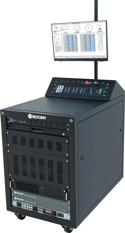
Gauging the performance of a BMS during r&d, validation, verification and production is therefore of vital and growing importance. Bloomy Controls’ new Flex BMS Validation System is focused on the validation part, particularly in situations where the developer needs to test more than one BMS design.
As the company’s founder and president Peter Blume explains, “The system’s signal interface panel makes it extremely easy to connect almost any BMS using industry-standard connectors and breakout boards.”
The system is designed for rapidly evaluating single-board, centralised and distributed BMSs through real-time simulation of a wide range of batteries, providing the cell and pack voltage, current and temperature signals along with the digital comms traffic, over a CAN bus for example.
Capable of gauging functional safety, it can run regression tests on hardware/firmware following modifications, and it can be used to tune SoC algorithms and to test application-specific configurations of a BMS.
A BMS under test would normally consist of PCB assemblies, Blume says. “It could be a single-board BMS that consists of just one assembly in a centralised architecture, or it could be a distributed BMS containing a main board that would run the processing functions, with multiple subordinate units doing the cell monitoring,” he adds.
However many PCBAs it consists of, the BMS under test would be laid on top of the Flex system’s console and connected to terminals on its signal interface panel. Using standard D-sub connectors and breakout boards eases reconfiguration, and the user interface is designed to be intuitive and allow model-based or direct input/output control of simulated signals, Blume notes.
As a battery simulator, the system is chemistry-agnostic. Being model-based, Blume says, customers can provide their own models, and Bloomy can supply an equivalent circuit model of its own, which will be offered as a toolkit.
As a standalone tool, the system can simulate up to 48 cells, voltage- and resistance-based sensors and pack charging and discharging at currents of up to 600 A through the BMS on test. It can also simulate and monitor all BMS input/output signals and comms.
Chief technology officer Grant Gothing explains that there are various ways of interacting with the system. When first exploring the system, customers tend to operate it manually, connecting their BMS, running a model, monitoring it and then creating a fault to see whether the BMS responds properly. “Once they get some confidence in it, they then switch to the automated side of testing,” he says.
The system automates two kinds of testing, he adds, the first being Safe Operating Area tests in which it presents the BMS with a simulated battery in a healthy state before injecting a fault, such as a cell overvoltage, to find out whether the BMS sets the right ‘trouble’ code and sends a command to open the main contactors at the right time.

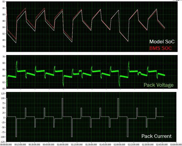
The other type examines the BMS’ response to complete drive cycles, for purposes such as algorithm tuning. For example, Gothing explains, in tuning an SoC algorithm the system compares the simulated battery’s SoC as calculated by the model with the SoC reported by the BMS.
Customers can specify their systems with up to four Bloomy Battery Simulator 1200 instruments built in for simulating up to 48 cells, Blume says, and there are options to test even larger numbers.
“If you want to simulate an entire 400 V automotive pack, for example, then we have the BMS HIL Test System, which has a different hardware architecture for simulating more than 200 cells,” he says.
With 12 independently controlled channels, this system can be stacked to mimic even larger packs.
ONLINE PARTNERS


