Charging ahead with Nyobolt’s SiC EVSE DC charger

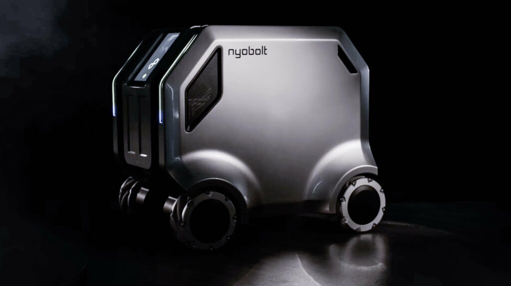
(Courtesy of Nyobolt)
SiC EVSE DC charger
Nyobolt has developed electric vehicle supply equipment (EVSE) for off-board DC fast chargers that integrates silicon carbide (SiC) power transistors.
Although the UK-based company most recently made headlines for its fast-charging battery technology, showcased in its eponymous EV (investigated and unpacked at https://www.emobility-engineering.com/nyobolt-ev/), the new solution is intended to enable highly-efficient charging stations as part of its vision of a more efficient ecosystem of materials and powers in the future EV industry.
“Rather than force OEMs to design a highly-efficient charger themselves, we’ve made one compatible with our fast-charging battery, which we’re going to be manufacturing and supplying ourselves,” says Iain Mosely, Nyobolt’s director of power electronics.
As of writing, the EVSE DC charger is an 800 V prototype module, configured for throughputs of up to 30 kW, which Mosely says equates to replenishing 120 mph.
Multiple units of this charger can be connected in parallel to increase the power level in steps of 30 kW. Nyobolt posits that a charging station and connector capable of 300-400 kW would be appropriate for a six-minute charge of the 35 kWh pack, as seen in the Nyobolt EV.
“Our modules utilise silicon carbide, which gives incredible performance with the lowest heat losses of any commercially-available power electronics component,” Mosely says.
“Over the vast majority of cycles, accounting for temperature and other variables, the charger transmits power from charging input to battery pack with greater than 99% efficiency.
“When we started the custom design, we had three target parameters to play with: the voltage capability, the current capability and the power output characteristic, and we had to tailor our system and these values in a way that would maximise our efficiency across all feasible environmental conditions, and states of charge and health.
Size doesn’t matter
“Often, charger manufacturers try to make the power output characteristic as wide as possible, so that it can charge anything from a Class 8 EV down to a little scooter, but that means a lot of power efficiency and performance gets lost. Our 30 kW module could certainly be used to charge a small e-scooter; it just wouldn’t be very power-efficient or cost-effective to do that.”
To explore which architectures and components worked best, Mosely and his team engaged in rapid prototyping in order to have numerous different charger modules they could test, connect in parallel and amass performance data on. Each module also ran embedded, real-time control software, which the power electronics team could tune for different parameters in their pursuit of maximum efficiency.
Principle among these parameters was the fundamental trade-off between switching frequency and power efficiency.
Energy saving
“If you want to reduce the size of some of your passive components, like inductors, for instance, you’ll push your switching frequency up and up. The trouble with doing that is that every time the power transistor device switches on or off, you’ll incur a small amount of energy loss,” Mosely explains.
“But SiC is one of the best technologies for minimising that energy loss, enabling us to push our switching frequencies higher without sacrificing that efficiency. The only problem is that SiC MOSFETs come in very specific voltage ranges – typically either 600 V for single-phase offline mains or 1200 V for three-phase automotive applications – so that slightly constrains us in what we can buy.
“That means in most cases, 800 V SiC inverter systems are technically capable of working in 1200 V architectures. There are other approaches, like multi-level inverters that can utilise two stacks of 600 V SiC MOSFETs connected in series, and those can bring down overall system costs in exchange for some extra design complexity, but to be honest, 1200 V is a very common ‘real’ voltage in automotive SiC applications today.”
Magnetic designs
Lastly, optimisation of the magnetics in the on-board charger’s transformer was key to providing an isolation barrier between the three-phase mains supply and the power electronics. This component was modelled in FEA to simulate for variables such as stray flux lines and loss mechanisms.
“Problems like these can get worse and worse for a transformer as your on-board charger goes up in frequency. As you get to really high switching rates, magnetics have trouble keeping up, as you get core and hysteresis losses, which can be very non-linear with frequency, not to mention skin effect in wires – high-frequency magnetics are an art unto themselves, so we have to take really careful control of how we design those to optimise performance,” Mosely says.
“There are plenty of choices of magnetic material we can feasibly work with, including ferrites, iron powders and others – it’s just a matter of understanding each material’s benefits and trade-offs. And, in addition to those, our custom digital controller for the charger really helps us to tune the performance how we want it, for energy efficiency, safety and so on.”
Click here to read the latest issue of E-Mobility Engineering.
ONLINE PARTNERS


