
")


")


Motor development and manufacturing
(Image courtesy of Additive Drives)
Principles of geometry
Peter Donaldson details the many processes involved in creating new motor systems
As with any sophisticated industrial process, the development of motor systems for e-mobility is a complex and multi-stage endeavour, subject to rapid change under pressure, both to innovate and ramp up to high production volumes.
The first stage is conceptualisation and definition, whereby key requirements are identified and the specifications of the motor are defined, based on the intended application, vehicle type, powertrain configuration and the regulatory standards that apply in the markets in which it will operate.
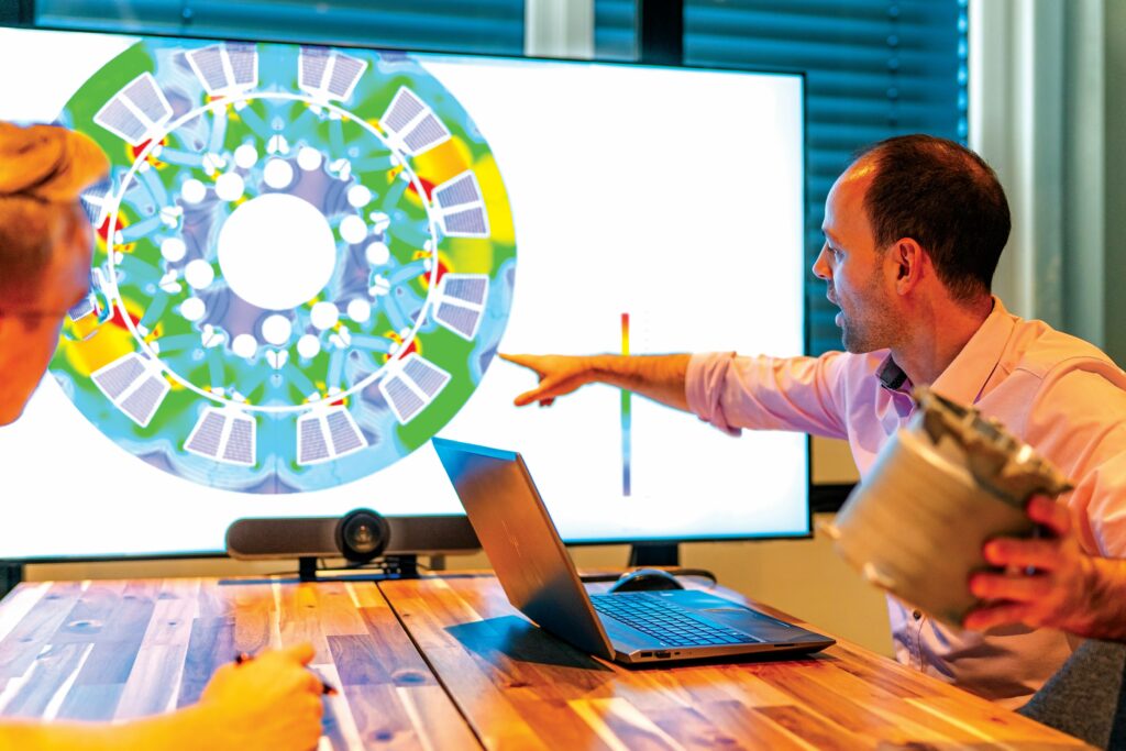
Next comes design to flesh out the details of the motor geometry, including the stator, rotor, windings, housing and design software, and the subsequent electromagnetic and thermal simulations to optimise motor performance, efficiency and cooling requirements. Designs are then validated using finite element analysis (FEA) and computational fluid dynamics (CFD) simulations.
Prototype development comes next, beginning with the fabrication of components such as stator and rotor assemblies, increasingly using rapid techniques such as 3D printing. Prototype motors are then assembled and put through initial bench testing to verify performance characteristics and validate simulation results.
More comprehensive testing and validation follows, focused on the prototype’s performance, efficiency and durability, including dynamometer tests that evaluate torque, speed, power and efficiency under a range of operating conditions. Thermal performance testing assesses the new motor’s ability to operate reliably within the design temperature limits, while durability testing helps to evaluate its longevity and resistance to mechanical stress, vibrations and environmental factors.
Data from these tests is used to inform iterative design modifications and optimisations to address any shortcomings identified during testing. Repeat testing and validation cycles are then carried out to ensure any design changes meet the desired performance objectives.
In parallel, the processes required for production are developed and tailored to the intended scale. Critical to this is optimisation of the methods for component fabrication and assembly, and quality control.
Making complete motors, particularly at scale, requires many different types of equipment, which, individually and together, represent large investments. These include the machines that wind copper or aluminium wire onto rotor and stator cores, and those that bend hairpin conductors and others that insert them into core slots.
Core manufacturing requires laser cutting or stamping equipment to shape the electrical steel laminations, and equipment to assemble them into the stacks that form the rotor and stator cores. Accurate alignment of the laminations is essential for motor performance.
Manufacture also entails machining multiple different components, such as shafts, housings and end-brackets using processes such as milling, drilling, tapping and boring. Increasingly, these processes are carried out with multi-tool machining centres – CNC systems capable of producing parts with complex geometries.
Insulation and coating equipment apply protective coatings to components such as the stator windings and rotor shafts to provide electrical insulation and thermal resistance, for example, and to enhance durability.
For motors produced in small numbers, manual assembly is often practical, but scaling up requires automated assembly lines with stations for tasks such as inserting coils into stator slots, joining stator and rotor assemblies, installing bearings and sealing motor housings.
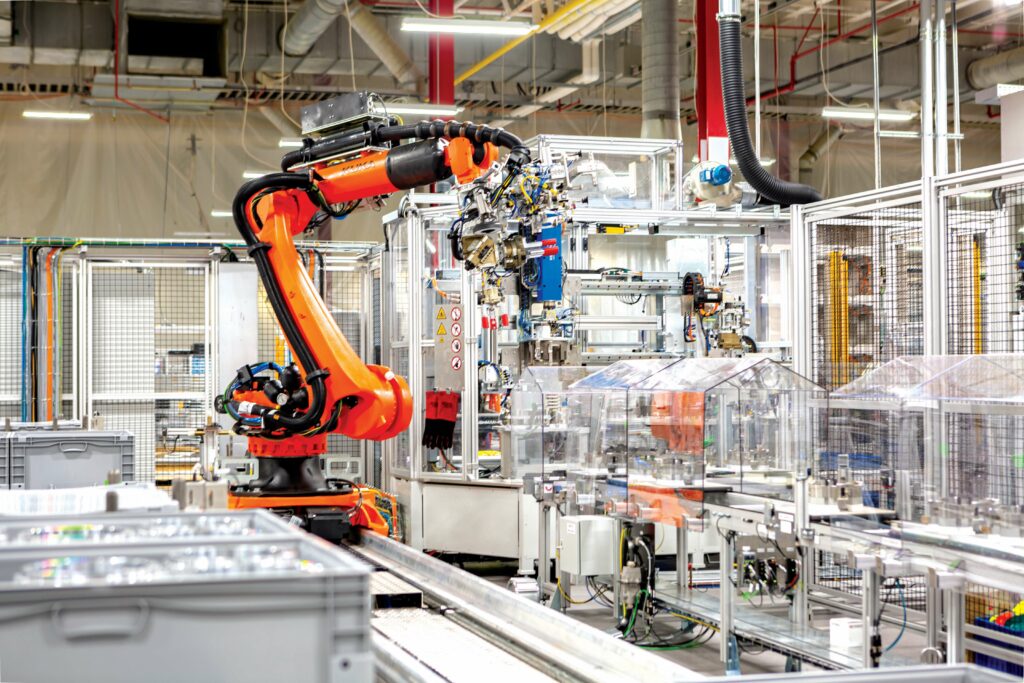
At practically every stage of production in a modern factory, material-handling systems such as conveyors, robotic arms and automated guided vehicles (AGVs) move parts between manufacturing stations, helping to optimise production flow and minimise handling errors.
Like all rotating machinery, motors have to be balanced to minimise vibration and optimise their performance, which is often completed on dynamic balancing machines.
Many of the above production stages have to be carried out in cleanroom facilities and are increasingly monitored by in-line, quality-control equipment.
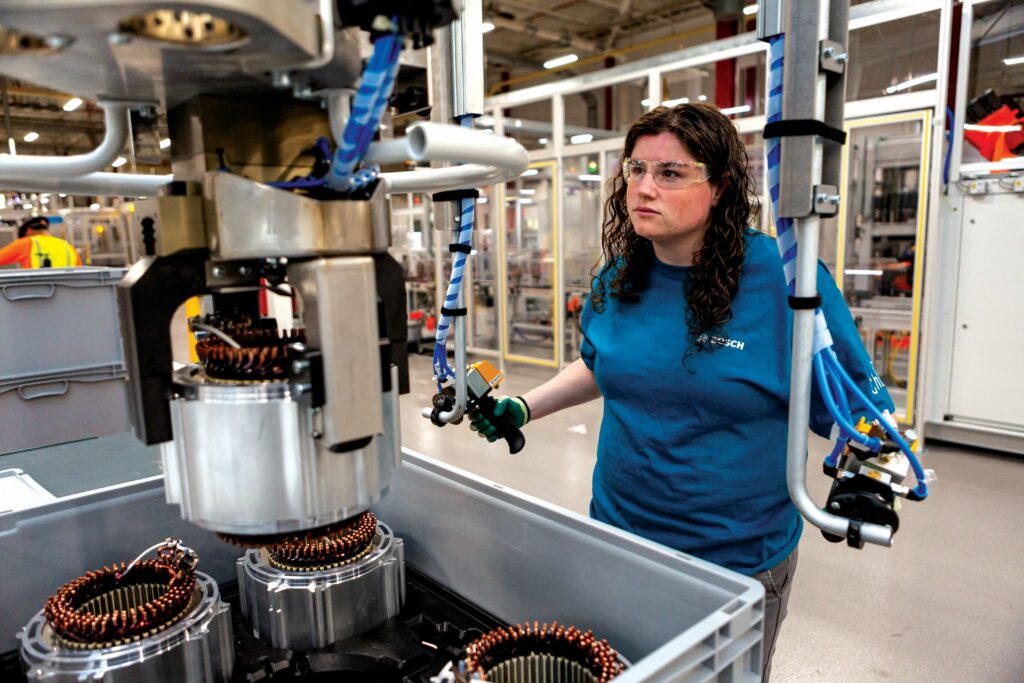
(Image courtesy of Bosch)
Capturing requirements
While there is no substitute for talking with customers, much worthwhile progress can be made in requirements capture, with well-designed templates for prospective customers to use, often presented in web form.
One motor developer we consulted gathers details on the installation space, electrical supply and cooling concept at an early stage of development in this way. This enables them to record and understand the existing system architecture as much as possible to fulfil requirements with customised designs.
“We use a design sheet with a rough calculation to make the designs plausible, taking electromagnetic, thermodynamic and fluid dynamic aspects into account,” an expert says. “The design sheets form the basis for the technology modules, the topology of the motor and the winding schemes, which are later detailed together with the customer, from which a design for manufacture is derived.”
Another motor developer says some customers provide detailed specifications in multi-page documents, while others make use of its web forms.
For example, on the company’s custom motor-design page, when a prospective customer clicks on ‘performance requirements’ they are invited to enter data on the machine type, DC bus voltage, maximum torque, continuous torque and stall torque, maximum speed, continuous speed, maximum and continuous output power figures, and the maximums for drive frequency and current.
A third developer stresses the importance of harmonising requirements from multiple market sectors and of conducting early-stage concept analysis to evaluate systems integration, according to its expert.
The engineering team also conducts frequent voice-of-customer (VoC) meetings to hone their understanding of the requirements. “We capture both the industry regulations and VoC feedback in one of the industry leading requirements managements tools. In forming concepts, we focus on simulation-driven design and rapid prototyping to shorten development,” the expert says.
“We work closely with our customers (who can be motor suppliers or end-users/OEMs) to understand their motor performance and design requirements during early development,” says an expert from a producer of speciality, soft magnetic alloys, and of stator and rotor stacks from iron-cobalt alloys.
“Then, we provide guidance on appropriate alloy selection, along with stack process/design solutions for preliminary prototyping purposes, keeping volume production in mind. Most of the time, our customers require either to improve the motor power or make the motor smaller using our stacks.”
A maker of stamping tools for a wide range of industries, including lamination dies for electric machines, takes a similar approach, starting in the quoting phase and providing feedback on design for manufacture (DFM) issues early on.
“The strip layouts of our proposed solutions help our customers conceptualise the final die design,” the company’s expert says. “This front-end effort ensures we are on the same page with our customers and that the final product will meet their stringent requirements.”
(Image courtesy of Bosch)
Design tool progress
Design and simulation software play an essential role in motor development, and several companies we consulted use packages from Ansys, including MotorCAD for overall motor sizing and concept development, Maxwell for electromagnetic design, Fluent for cooling optimisation, and Mechanical for finite element analysis (FEA) work. One mentioned using JMAG Designer for electromagnetic design, while another said its engineers use SolidWorks from Dassault Systemes.
One major automotive systems developer uses a mix of commercially available software and its own tools to meet specific needs. “For the e-motor simulation and optimisation, our own tool chain that contains all our production know-how is key,” its expert says.
“Typical market tools have too many restrictions at interfaces, which limits their flexibility in building optimised tool chains. Development of our own integrated tools is a key element in our overall product strategy.”
Using Matlab Simulink, our third motor developer has created a tool that models motor duty cycles, aiding customers’ understanding of system-level motor behaviour. “This tool allows the input of duty cycles and system conditions to model the motor’s predicted thermal behaviour early in the development cycle, providing confidence in system sizing across the powertrain and cooling circuit,” its expert says.
Engineering software is now more powerful and generally more user-friendly than ever, although it is still important to choose the right tools for the job. There is a broad variety of tools, some of which require a low level of electromagnetic (EM) design expertise to get a rapid understanding of the basics, while the more sophisticated tools demand a lot of expertise to use them, according to our automotive subsystems developer.
The expert says the progress made since the initial software releases 20-25 years ago is phenomenal, and the tools serve the key needs of the industry very well. “However, all tools require a perfect understanding of material properties before and after process steps to be able to simulate reality.”
The soft, magnetic alloys specialist says simulation tools are extremely important to design and improve motor responses, enabling engineers to perform motor design optimisation quickly, while facilitating the choice of materials, dimensions, windings and housing types, along with specific design features.
“Previously, these tools did not have large, built-in databases, but now more and more are becoming available,” the expert says. “For example, specifications for several of our materials for stators and rotors that were not readily available earlier are now available in the simulation databases.”
The advent of 3D software such as SolidWorks has taken design engineering to the next level, according to the lamination die maker, because it enables the creation of detailed, realistic models that can be viewed and manipulated from any angle.
“This enables engineers to visualise the final product more accurately, identify potential issues early on and make adjustments,” the expert says. “It also enables engineers to simulate the performance of the design, optimising it for efficiency and effectiveness.”
Thanks to customised software, engineers can get from a concept to a final design more quickly than before, and make very good predictions of motor characteristics, says one of our motor developers. “In particular, the comparison with measurements on the test bench gives us a good understanding of the motor’s performance, which we can use for further development.”
Our second motor developer notes there has been a drive towards system-level optimisation capabilities in the software, enabled by the integration of different tools.
“With MotorCAD, for instance, you can design your motor and then bring it into Matlab, where you can then look at optimising your system,” its expert says. “For example, I could design a 99% efficient motor, but if I were to pair it with a controller that has to switch at an excessively high frequency, it is then going to have such large losses in the inverter that overall the system would be a lot worse.”
This is particularly helpful as customers are increasingly asking for turnkey solutions. “A lot of the change in my job over the last couple of years has been in offering full-package solutions – so, motor, inverter, gearbox and even battery packs, working with other companies.”
Integrating individual tools with one another allows for multiphysics analyses (in Ansys Workbench, for example), which our third motor developer regards as a major improvement in design and engineering software.
Its expert notes this has greatly reduced design cycle times and improved the optimisation of designs across independent domains. He credits Ansys OptiSLang with easing the integration of optimisation into the design simulation loop, offering new ways to ensure local optima are avoided.
(With optimisation problems, local optima are solutions that are better than neighbouring ones, but not necessarily the best overall. The software enables thorough exploration of the design space, increasing the likelihood of finding a global optimum solution.)
The expert also cites the emergence of cloud-based, high-performance computing (HPC) as a key enabler of the use of advanced simulation tools in design and development, with agility bringing agility to the process.
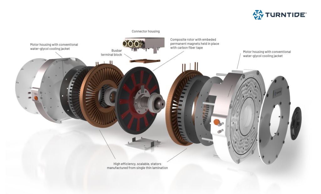
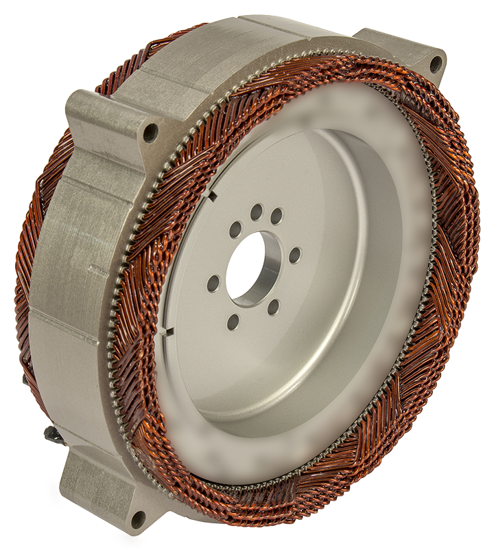
(Image courtesy of Turntide)
Creating prototypes
Moving on to hardware, companies that provide prototyping services often make their own tools. For one organisation specialising in building prototype e-machine rotor and stator lamination stacks from customers’ CAD files, this is almost a routine task.
“For every item that we have to manufacture, we have to engineer a new device that works as an aligning and pressing tool at the same time. The laminations are placed one-by-one into the tool and pressed down, and then they can go into an oven if they are bonded using Blacklack, or onto a welding station to create a solid stack,” its expert says.
Companies emphasise different aspects of prototyping. One of the motor manufacturers we consulted says they start with an analysis of customer requirements to see whether an existing design meets them or comes close to doing so.
An expert from another motor manufacturer follows his assessment of customer requirements by establishing and communicating basic assumptions. “It’s really good to clearly write down what I’m assuming so it can be revisited later, because otherwise some important things you think should be obvious to a customer might not be.”
Some high-level initial analytical equations might then be run for sizing the motor, followed by an initial concept review in which you would evaluate rotor topology. “Then you would use something like Ansys MotorCad to analyse feasibility and validate your sizing equations,” he adds.
Next comes mechanical, electrical and thermal optimisation in 2D and then 3D. Mechanical optimisation of the laminations would be done with a 2D tool, but some losses, such as those associated with eddy currents in the stack or ohmic losses in the end-windings, can be calculated more accurately with 3D tools, he says.
When the time comes to make prototype hardware, the company will 3D-print a stator to check that the winding pattern generated in the CAD system can be wound in reality. While most can, it is not always the case.
For example, if the motor uses stranded wire there is a degree of uncertainty and the engineers consult with experienced winding workers, who might change the order in which the coils are wound or perhaps identify an opportunity to increase the slot-fill factor.
An expert from a different motor developer says the company was starting to make the prototyping of new e-motor designs easier, better and faster.
“To achieve this, we rely on the targeted use of 3D printing to realise complex designs without the use of complicated tools,” he says. “We produce 100% comparable prototypes of hairpin or wave-wound stators in just four weeks, and support well-known tier ones and OEMs in their prototyping processes.”
The company creates motors with many different topologies, including synchronous, asynchronous and axial flux machines. “In addition, our 3D printing processes enable new winding-head designs and conductor structures, for which we also rely specifically on 3D simulation,” he explains.
“We have used additive manufacturing techniques to assess our designs at very early stages to check the feasibility of some of the more challenging aspects of manufacture,” another notes. “We have also found that lead times for prototypes have greatly reduced as there is more competition in the low-volume manufacturing space.”
The key technologies for any stator are around wire forming, wire insertion and welding, notes our major automotive systems developer. For hairpin technology, the twisting operation comes on top, he adds.
The company makes extensive use of commercially available, CNC wire-forming technology, of which recent advances have significantly improved flexibility for prototyping, in addition to some specialised equipment of its own.
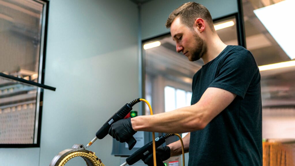
Testing and validation
(Image courtesy of BorgWarner)
New motor designs must go through the challenging processes of testing, validation and, if necessary, further optimisation and iteration.
“We try to break down a lot of testing to the individual components and, for example, to test conductors or conductor pairs for qualification,” our first motor developer’s expert says. “Based on these test results, we draw conclusions about the behaviour of the assemblies before they are finally put together.
“We do end-of-line tests on every stator, sometimes with very high voltages, to ensure our parts are of the best quality and reach the customer safely. Of course, we also validate our simulation results on the test bench, but we have a very good tool chain that provides us with the desired results during the design phase, so that we can keep the number of iterations to a minimum.
“Finally, we carry out accelerated life-cycle tests on the overall motors and mirror these back to the results of the individual components to check whether they meet expectations.”
Mathematical models are used to predict service life and failure probabilities, with parameterisation being a major challenge, the expert says. “The basis for this is formed by various test scenarios, which we customise in order to achieve the best results.”
Parameterisation is the process of determining and setting the values of the variables (parameters) that characterise the model and influence its behaviour. It is a challenge because motors are used in diverse environments, and they are subjected to varying loads, temperatures and usage patterns.
The process requires a lot of data on motor performance and failure incidents under many conditions (which may be incomplete) and often involves the use of complex statistical methods and algorithms. It also demands detailed knowledge of physical degradation mechanisms and environmental factors.
Price pressure is significant, our major automotive systems developer stresses, explaining that optimising the bill of materials (BOM) to meet both technical and financial requirements is the most important aspect for any product’s development.
“This demands a high degree of cost awareness in the technical project team, and the flexibility to introduce innovative technologies and materials from any potential new supply chain offering quickly,” the expert says. “The key challenge is time in all aspects of project execution, from design and supply chain evaluation up to testing and validation.”
He adds that the testing process presents a complex problem that engineers break down into smaller steps that can be executed quickly; for example, in the validation of insulation systems. “We developed our own testing methods, helping us to significantly speed up the time required for base validation. Nevertheless, the final product must undergo complete durability testing, but only for final confirmation of its conformance with requirements.”
Lead time can be a major issue in prototype testing, often driven by specialist materials, our core stack manufacturer points out.
Its expert says: “In general, the material/alloy lead time related to iron cobalt alloys has been significant (say, 20 to 26 weeks) followed by stack manufacturing (another 18 to 24 weeks), so it can take a very long time to assemble prototype motors and perform the first tests, which generally takes another three to six months.
“Design verification/validation and freezing takes several iterations, making motor development a multi-year cycle. For fast-moving applications, such as urban air mobility (UAM), the development cycle needs to be much shorter,” its expert says.
The company has reduced its lead time on iron cobalt alloy stacks to 10-16 weeks. Furthermore, it uses testing techniques that enable motor designers to see the finished stacks’ magnetic responses as they are supplied. They can then use these results to simulate/predict motor responses, which in turn allows them to optimise subsequent processes, such as winding and housing design, to maximise performance and shorten the design iteration cycle.
For motors intended for use in a wide variety of vehicles and environments, particularly if they are off-the-shelf products, it is impractical to test for every condition it may meet in service, says one of our developers. “Probably, the biggest challenge for an off-the-shelf product is testing broadly enough for a lot of different applications, but deeply enough that you can stand behind your product and really feel confident in it.”
Test standards such as ISO 16750, which sets out the environmental conditions and testing procedures for electrical and electronic equipment in road vehicles, provides a useful benchmark for planning tests, says another developer.
However, to ensure planned tests match the risks presented by the design environment and the predicted behaviour of the system, they should be “thoroughly investigated” against the design failure mode and effects analysis (DFMEA), and the system failure mode and effects analysis (SFMEA), its expert says.
(The DFMEA is a detailed analysis component design and function that looks for ways it could fail, and how such failures could affect the system as a whole. The similar SFMEA focuses on the entire system, and is used to assess potential failure modes, along with their causes and effects.)
Motor performance is typically characterised by continuous and peak torque delivery, which are useful metrics for comparing motors and basic sizing. However, few motors are operated at either point in real-world applications, the expert adds.
Traditionally, validation testing takes place late in development, which is a large source of risk if problems emerge. To reduce this risk, the company has invested heavily in simulation to evaluate performance and in its own in-house testing capabilities. “This allows early prototypes to undergo representative testing and subsequent feedback to be looped into the next design iteration.”
The expert explains that motor and inverter testing and validation require dedicated, back-to-back dynos to characterise the motor throughout its operational envelope.
(Image courtesy of Additive Drives)
Scaling up
Manufacturing at scale can be seen as a continuum between what are essentially assembly and integration operations at one end to fully vertically integrated ones, with everything from raw materials to finished motors under the control of a single organisation, at the other end, but most fall somewhere in between.
According to our soft, magnetic alloy and iron-cobalt stack specialist, the push for higher motor performance has led to the adoption of adhesive-based bonding and thinner laminations, in place of interlocking, in the automated manufacture of the latest-generation of EV rotor/stator cores.
“The new e-mobility vehicles will require hundreds to thousands of stacks per model per year,” its expert adds. “We are working on new, automated stacking and bonding technology for larger-scale production. The use of robotic handling, machine vision alignment and feedback sensors will boost productivity, and improve the repeatability and quality of iron-cobalt stator and rotor stacks.”
One of our developers makes its customised motors almost entirely in-house and in quantities of one to 100,000 without complex tools or high, one-off costs. “We even use our own wire-drawing machine to keep delivery times short and to be able to produce special wire geometries. The production of the active parts of the motor is our core business, with all production taking place in-house,” its expert says.
Working with customers from development to production, the company has its own automation team. This enables it to realise fully automatic, fast production of X-pin, wave winding and hairpin windings in individual designs, and to react quickly to changing requirements. It can also automate the production of stators, rotors for synchronous and asynchronous machines, and the complete assembly of motors.
“Almost exclusively, we use rectangular profile wires for the manufacture of our motors. This means we attach great importance to bending processes,” its expert says. “We have the opportunity to combine conventional and additive manufacturing into a hybrid approach, and thus make additive manufacturing scalable. We are also proficient in various forms of laser welding for the production of stators in large quantities.”
While in low-volume production it can make sense for a worker to spend a couple of hours or a day, depending on the motor, to put the windings onto the stator/rotor cores, as soon as you start manufacturing at scale it isn’t feasible to have that kind of takt time, according to another expert. “Automated winding is really key as you start scaling up.”
He says it can be hard to automate the winding of stranded wire. “When you’re getting towards the end and looking at clamping all those materials together to create your star point or form your end winding, it’s sometimes difficult to know exactly where each strand of wire is.”
With automation of hairpin windings, however, cameras and image-processing software can compare the positions of the hairpin ends before welding.
While assembly processes remain essentially the same, the expert says they have to be rethought to take the human element out. With “hot dropping” of a thermally expanded motor casing over a stator, for example, very little tooling is required if it is done manually at low volume. A worker might put the housing in an oven, take it out, push it over the stator with gloves on, and allow it to cool to achieve an interference fit – with the only tooling required being a step fixture to prevent the housing from being pushed too far.
Automating the process would probably need more than one machine, however. “You would use induction coils to heat that housing up while a robot held it, and then the robot would take it onto the next stage and hold it over the stator, where pneumatic rams would push it on, and then you would force-cool it,” the expert says.
Running sub-component production alongside the main manufacturing lines, so they can feed into them, facilitates tight quality control throughout the entire process, another expert points out. This is critical, both through upfront inspection with automated, coordinated measuring machines (CMM) and after production with end-of-line test dynamometers, he adds.
As manufacturing technology continues to evolve, the company expects greater emphasis on and advancement towards full automation of production and material handling.
“This includes flexible tooling, fully automated axial stator-winding machines, improved additive manufacturing processes for mass production, and the introduction of higher insulation class, high mechanical performance, lightweight materials to improve the weight and efficiency of motors,” the expert says.
(Image courtesy of Turntide)
Acknowledgements
The author would like to thank the following for their help with this article: Jakob Jung, chief executive technical officer at Additive Drives; Rolf Blissenbach, chief engineer, e-drive generic & platform, and Bernhard Schmitt, global engineering director, electric motors at BorgWarner; Jaydip Das, senior manager, applications engineering at Carpenter Electrification; Red Blaylock, traction leader at Inetic; Barry Lee, VP, technology at LH Carbide Corporation; Adam Nixon, head of engineering for motors, Matrishvan Raval, head of product, and Gary Stevens, thermofluids & emag engineering lead at Turntide Technologies.
Some suppliers of motor development & manufacturing
Additive Drives
BorgWarner
Carpenter Technology
Danfoss
Equipmake
Grob werke
Helix
Inetic
LH Carbide
Marposs
Syensqo
Turntide
Traxial
YASA
+49 3731 274 5047
+1 248 754 9200
+1 610 208 2000
+45 74 88 22 22
+44 1953 661200
+49 8261 996-777
+44 1908 278 600
+44 1264 334 095
+1 260 432 5563
+39 051 899111
+32 2 264 19 00
+1 408 402 4051
+32 499 22 52 25
+44 1865 952 100
ONLINE PARTNERS


