


")


")
HIL Testing
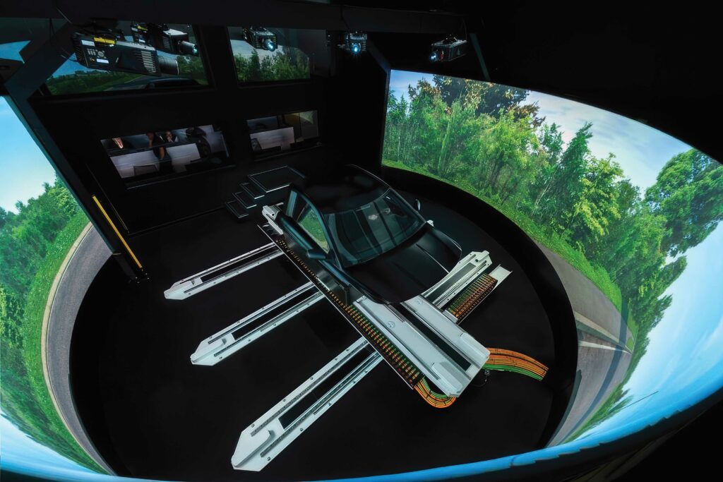
(Image courtesy of Ansible Motion)
Digital gets real
Nick Flaherty traces the line where digital models of components meet simulation to experience a vehicle before it is even built
Virtual design methodologies are increasingly being adopted in the development of e-mobility platforms – combining digital models of components with simulation to create a digital twin of an entire vehicle that can be driven before it has even been built.
The drive and handling experience of a vehicle is fed back into the design process, allowing the battery pack and powertrain to be optimised with different topologies and chemistries, all of which can be modelled in the digital twin. Similarly, the noise, vibration and harshness (NVH) resulting from all the components through the tyres and suspension can be analysed and reduced.
As the development of the platform advances, real devices such as the electronic control unit can replace virtual models, adding hardware-in-the-loop (HIL). This allows ECUs to be tuned for optimum balance of performance, range and reliability long before a vehicle hits the test track, potentially saving millions of dollars and months of time in the validation testing process.
HIL can also provide predictive analysis. Running a simulation faster than real time can give data on how the components behave over time, identifying parts that are more likely to fail earlier than expected under particular driving styles. This isn’t a pipe dream. Developers are aiming for an end-to-end entirely digital design process where HIL is a key element.
“We are working towards a digital by default design process by 2028, and HIL is a great route to getting there,” says Phil Langley, strategic and business development manager at tier one supplier ZF.
Salman Safdar, business development manager at Ansible Motion, says: “We are seeing a major shift. If you have your model and you want a human to experience that, you need us to bring that human into the virtual environment to bring in the realism of the virtual hardware.”
(Image courtesy of VI-grade)
Integrating simulation
Physical simulation system developer VI-grade is linking its dynamic simulator with HIL systems to test more parts.
“We are known for vehicle dynamics and simulators, and that plays an important role as everything interacts. Then we were asked to deploy other aspects on the vehicle, with the interaction with the powertrain and also the subsystems, such as the suspension, steer-by-wire or brake-by-wire systems,” says Alessandro Baldari, European sales manager at VI-grade.
The dynamic simulators are based on a patented concept where the lower part moves on air pads with three main actuators or cables to give a realistic driving experience.
“Our work starts much earlier in the design process, long before the physical hardware is available, so our initial approach is not in HIL but in the early X-in-the-loop, where only the models are available, so we form a basic model to a more complex, validated, physical testing, but still at the model level.”
“Then, we move to software-in-the-loop (SIL), where the exact specific software of the ECU is running at real time at 1 kHz for vehicle dynamics, updating every 1 ms. We can control all the sublevels of the simulation, so we make sure every calculation is performed in that 1 ms,” he says.
“Control systems and test rigs run faster at 4-8 kHz, but those exchange information with the driving simulator or the real-time test system every 1 ms. This is a common understanding for automotive applications.”
The SIL covers the ECU with the exact communication protocols, such as CAN or FlexRay.
“At every level you can have a mix of models, and as the products mature you can integrate the HIL, ECUs and subsystems with the proper communication protocols. ECUs can be open and reprogrammed, or they can be black box and fixed, and this is a very strict HIL definition,” Baldari says.
“Mechanical HIL is a further stage, where you can use test rigs to include physical components, brakes, steering, connected to the real-time simulation, so you can have different simulation models or drive those test systems, and this is mechanical HIL.
“The very final stage is a full vehicle where some of the components are missing – the vehicle-in-the-loop – where you can run on the vehicle in real time or faster than real time to replace ECUs that are not available.”
This can be used to predict physical issues by using data from physical sensors such as radar or from the suspension system to anticipate braking, or for a rear-wheel steering system to see how the system performs over time.
“At the model-in-the-loop (MIL) up to SIL you want subjective feedback,” he says. “You can run offline simulation first to find the optimum for performance, energy consumption; then select the experience for those selected ranges.
“For example, you can have the best lane-keeping algorithm, but when you drive it the control system is a poor experience, too aggressive; then you move from the objective data to the subjective feel.”
“With an advanced model, you can test energy consumption, the kWh/km, but no matter how long you run offline simulations, sooner or later you’ll need to drive that powertrain.
“If you don’t drive it you will need to do a lot of tuning later on, and that’s very time-consuming and costly, so what you want to do is drive the vehicle virtually, and assess the quality and realism of the drive of the subsystems as if they are physically mounted on the vehicle, so you need a proper vehicle model, a proper motion platform, that is as close as possible to reality.
“The components are interacting with other components, so you need to experience the whole assembly of the vehicle.”
“If you test a physical component, you can find it’s 18 months before you have the full vehicle and find out if that component being developed is good enough – that’s the real advantage to having the HIL in a real-time simulator.
“There is no better test bench than a human being. You don’t know how the driver will behave. Different drivers will behave in totally different ways, for example, to avoid an obstacle – professional drivers, the less experienced, new drivers – but you still need to have the vehicle respond in a safe way and interact with sensors that help the driver,” he says.
“This enhances the quality of the test; for example, on the Nuremberg ring there will be many runs, and every single one will be different and the powertrain response will be different as it will stress in a totally different way. What is the right one? All of them are right.
“A few years back there was a limitation on the compute performance as it was expensive. Now you can have a full, multi-body system with hundreds of degrees of freedom for the chassis, suspension brackets, and still run in real-time using multicore, multi-CPU technologies.
“What is really limiting right now is that the full digital twin is not at the model level but at the HIL with the ECU. These are developed by the tier one suppliers and they want to hold onto this technology, and that part is really time-consuming. There is a trend from OEMs for in-house development for software, leading that development and not just modifying what comes from the tier one supplier.
“That’s why the customers, OEMs and tier ones want the complete ECU with a complete replica of the ECU, and then you start to look at the functionality, but that’s too late and expensive. Instead, there is a unified protocol for exchanging data between the ECUs. The problem is that most of the ECUs are black boxes.”
This can be a challenge. For example a black box ECU for the powertrain provides the inputs and outputs for the ECU, but the system also needs the inverter model and the battery management system (BMS) for more data for virtual development.
“If you don’t simulate the rest of the bus connected to the battery pack, the BMS will go into safe mode and will not work,” he says.
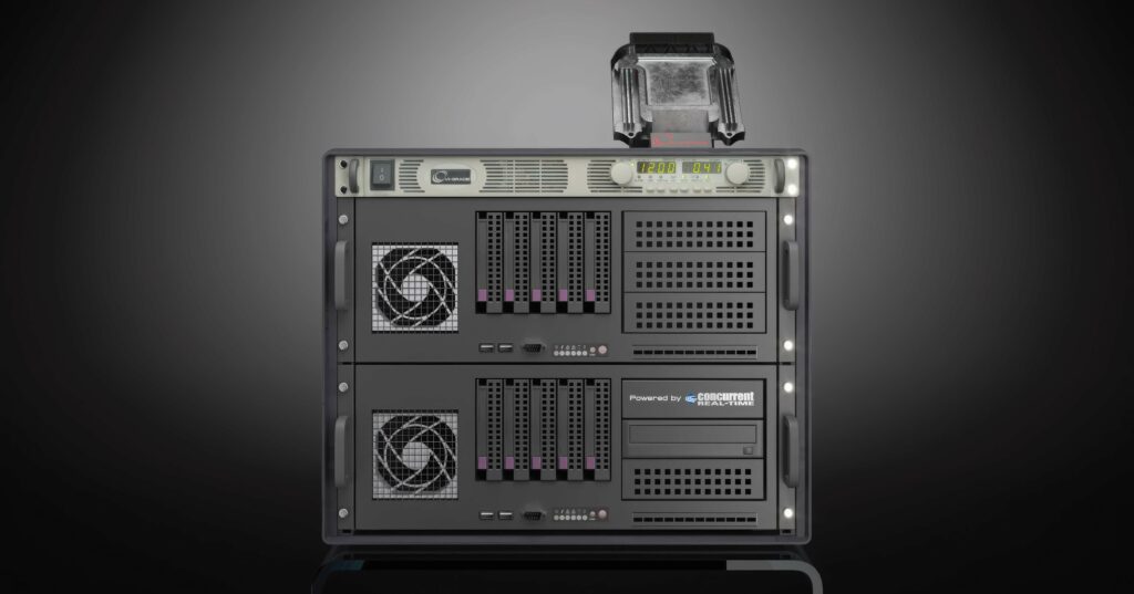
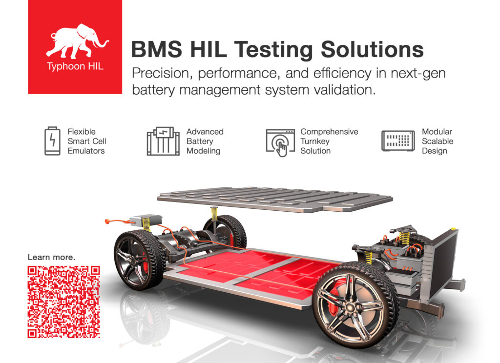
(Image courtesy of Typhoon HIL)
Custom hardware
Typhoon HIL is extending its simulation and emulation to model chargers and battery management. The company has developed an emulation system for power electronics testing, including powertrain development, based around an array of field-programmable gate arrays (FPGAs).
“We specialise in HIL for power electronics, with a focus on motor drives and chargers in e-mobility applications. While we can model ECUs for motor drives, onboard chargers and BMS, our HIL system is specifically designed to test real ECUs, ensuring reliable and high-fidelity validation,” says Petar Gartner, director of HIL Solutions at Typhoon HIL.
“When we talk about HIL, we believe the value is at the signal level, so you have a controller ECU exchanging signals. While we do support signal-level interfaces, BMS hardware requires higher current than our base devices can provide. However, since there’s no real power transfer involved in this approach, it remains both safe and flexible.”
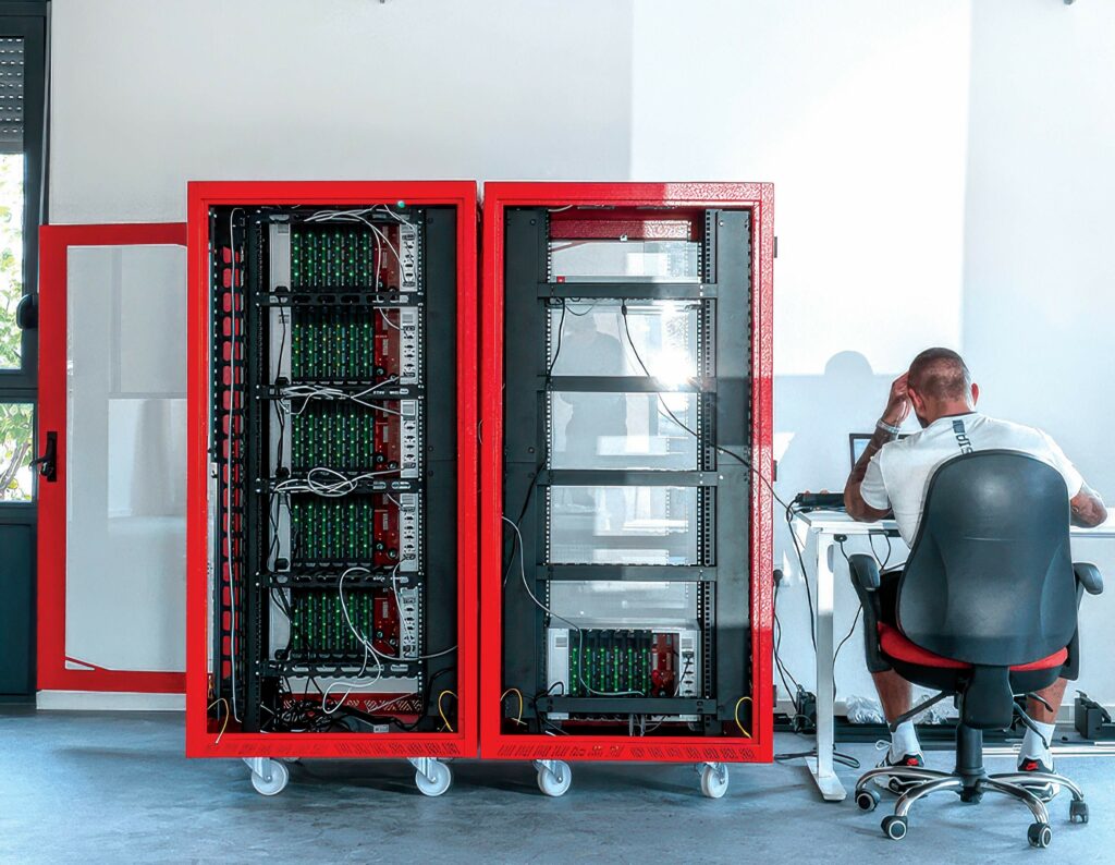
The hardware interface emulates the physical signals of the battery cells with the voltages and currents. A parameterisable model running in the simulator replicates different discharge characteristics and thermal behaviour, generating signals that pass through the signal-conditioning unit before reaching the BMS.
“This gives us full control, as besides the hardware, we make the software tools, the models’ vertical integration, and we are quicker to adapt to the customer, so we don’t need to make sure we are fully compatible with third-party vendors.
“Typically, we see voltage ranges from 350-850 V and, depending on how the customer arranges the cells in series or parallel, we choose the appropriate number,” Gartner says.
Each card emulates up to four cells from 1.5 V to 3.5 V. There are six cards in a rack, and up to 16 racks in a unit.
This approach allows for physical fault insertion. “What you can do is disconnect a line, reverse the voltage. And, also from the model, you can insert disturbances, electrical noise and that noise would propagate to the output,” says Gartner.
There is a controller area network flexible data-rate (CAN FD) link from the central processing unit to the cell emulators as different nodes.
The parameterisable model supports a range of chemistries and different models from Simulink or other tools. This uses the Functional Mock-up Interface standard for simulation model exchange, or developers can port C-code to the tool and compile to processor and import the compiled code.
The software environment for modelling includes drive models and converter models to build a system using a drag-and-drop interface, and this is downloaded from a PC to the HIL to run on the FPGA array. For example, this could be a model of a two-level inverter with six transistor switches and three-phase permanent magnet (PM) motor.
Typhoon has built its own specialist processing system that is implemented as custom logic on the FPGA and runs the design, avoiding the need for designing or compiling a design for an FPGA, which can be challenging.
“We built a processor architecture on the FPGA, and use different modules and translate to the architecture,” says Gartner. “This gives us flexibility and control over the whole model, and the users don’t need third-party tools as the FPGA is pre-compiled.”
Developers can use the system to test the physical ECU. “The time-step of the simulation is important; for us this is sub-microsecond, typically 250 ns, for a drive system,” Gartner says. “The other thing is the latency from the control signal coming into the ECU on the outside.
“This is in the microsecond range for us, through the analogue to the digital converter (ADC), apply to the model, and then the digital-to-analogue (DAC) conversion on the output.
“For an inverter, we track the thermal effects, the losses in the motor, and we can track in real-time. For the motor, the more detailed the model you can run the better it is, so we model and simulate how flux saturates with the currents, and how the field is impacted by the geometry and the slots.
“We can import that detailed data from the customer with their measurements. We cover a range of fidelity for the model, increasing the level of fidelity through the development process as the data improves.”
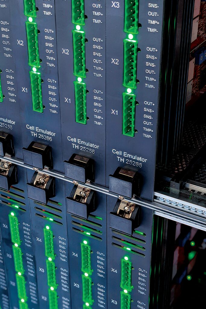
(Image courtesy of Typhoon HIL)
Digital backbone
“A few years ago, people came to us for a subjective assessment through a driving simulator, but the simulator is just one aspect with MIL and mechanical HIL,” says Safdar at Ansible Motion.
“We get involved right at the beginning of any development, from the components to modifying existing base models of vehicles. We can quickly load the models on the system, and put a driver in the simulator to tell developers how a driver will feel with handling, safety and performance.
“We are finding engineers are becoming much more bold in trying different concepts. Now they can push the boundaries with less risk.”
To do this, Ansible has developed a databus technology that allows all the different HIL technologies, testbeds models and simulators to be combined. The distributed data bus (DDB) is driven by a network of Windows PCs with software developed by Ansible.
A traditional simulator connected to a powertrain testbed can cover 80% of calibration and then take it on track for safety validation. This federated HIL system offers the ability to do 95% of calibration. The next step is a dynamic platform with six degrees of freedom (6DoF) for 100% validation, he adds.
“Dampers are difficult to model in the virtual environment. We have done an integration with four active damper systems with individual attributes when driving on the road, monitoring the dampers, so we’ve taken it to that extreme.”
“The third area that’s difficult to create a good model for is the steering. That’s a nightmare for integration, and we worked with MdynamicX for the physical hardware and integrated their technology into our simulators, so what we offer now is way beyond just the driving simulators.
“In our distributed data bus we align the time stamps and synchronise the signals, and present them in real-time to the driver, so we have data-logging coming from different areas, the vehicle physics, and then we take control of their software, which goes into the DDB and then into the motion-control PC. Then we have a growing network of HIL applications, from an IR sensor model to a full powertrain testbed, and even connecting four or five testbeds to have multiple vehicles for sensor interactions.
The DDB bus is based on user datagram protocol (UDP) Ethernet packets that offer more deterministic links than other Ethernet protocols. “UDP is accessible by most software, so we’ve made it open and flexible to allow developers to write their own drivers to blend into the platforms,” says Safdar.
“If you look at the structure of the control system we have deliberately created partitions so the audio has a separate stream, graphics, motion for the motors, HIL – separate for data, separate for physics – and we evaluate how much processing power you need, depending on the refresh rates and size of the packets. We can connect up to 18 PCs, but the maximum so far has been 11, so there is room to expand.”
“The other thing is the software. There is an office-based version and the real-time version. Depending on which physics engine you are using, it is Windows-based, so if the software demands Linux for real time we can bring in a third party such as dSpace, NI or Speedboat into our system, and we provide an interface. This is where we are spending a lot of time designing the system as it’s very diverse.”
For example, OEMs can run real-time models of different tyres at the DDB level to test vehicle performance under varying conditions.
“So there are very different ways to bring those models and data back into the system to keep flexibility, with multiple physics engines and multiple tyre engines to test out the options.”
The same applies to testing battery technologies in different virtual vehicles and driving them in a simulator to see how their performance changes.
“We are seeing a lot of people doing this in tools such as Matlab where developers write their models. The thing with our system is you can change the chemical properties of the batteries on the go, so that can give you different weather configurations, changes to the motors, and change the weight, the aerodynamics. Currently, it’s the weight versus the range of the battery that’s the concern – that is the biggest topic we see right now,” says Safdar.
“We can integrate the battery models into a car of their liking, and that changes the properties of the vehicle, changing the pack density, handling, road grip, and what that means for the range. We are seeing a lot of complaints from end-customers about the ride and comfort of EVs with the low centre of gravity and heavy battery packs, and this helps focus on the balance of comfort and range,” he adds.
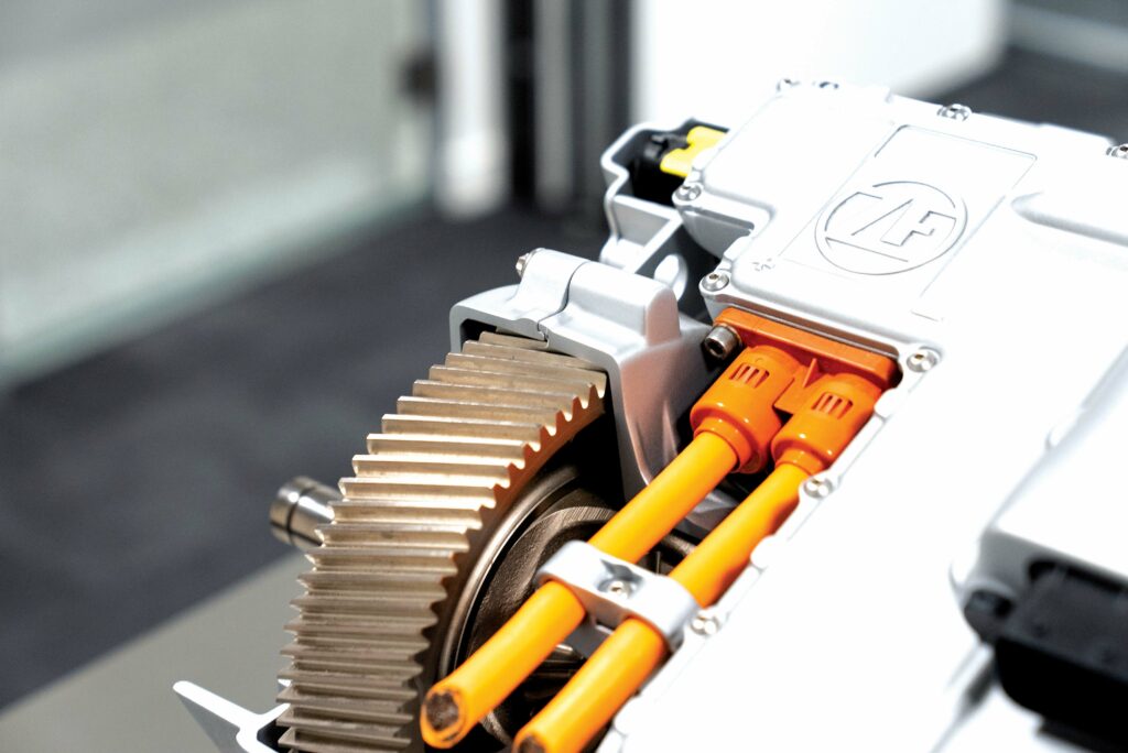
(Image courtesy of ZF)
Custom rigs
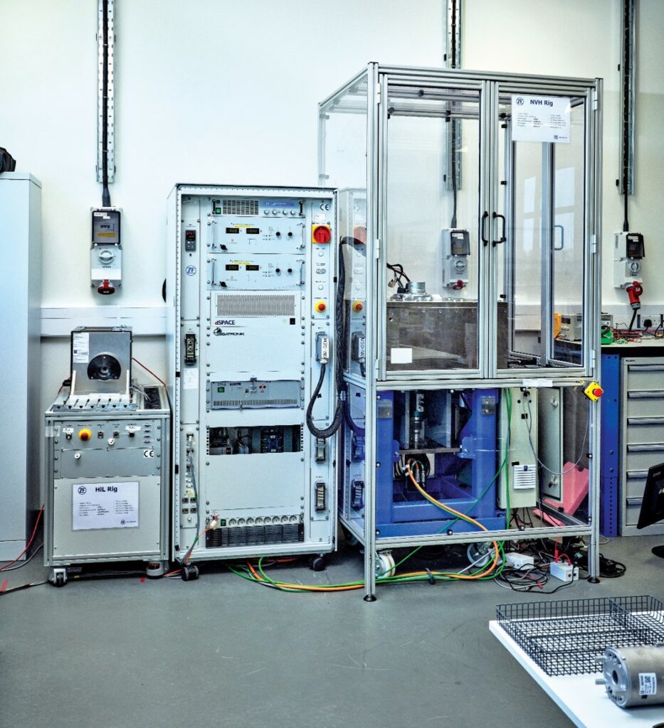
ZF is using HIL and model engineering in its r&d department for servo drives for noise, vibration and harshness (NVH) testing of vehicles. The company has developed a custom system that combines two HIL systems.
“We have a DSpace controller with two consoles – a traditional dynamometer arrangement with a drive motor and with a torque cell. With something like that we can get the dyno to replicate a load, and at the same time the model that is in the HIL can get the unit under test away.
“What we have done is added a second console that we can use for NVH, and in particular structural noise. In EVs, everything is so much quieter and we want to look at this,” he says.
“We designed this ourselves, and it’s similar to the dyno with a drive motor and a large metal rig on rubber mounts, and we can put the unit under test (UUT) on top; for example, a steering motor. We can then measure the structural noise from the unit at the same time as applying signal to the unit, and create a load condition of the environment using the HIL, so we can use it as a simple dynamometer or to recreate a particular situation in the labs where it is much easier to investigate particular factors of operation.”
“For us, it has been a really useful facility, as with the HIL rigs you can do lots of tests, automate them and simulate parts of the system you haven’t got available early in the development cycle. Having the HIL rig allows us to do that. We have the models in the rig, creating the situations that the UUT can then see. It allows us to get insights that would be very difficult to do otherwise.”
The models are developed and maintained by the HIL tooling team in Dusseldorf, Germany, and they maintain all the models for different types of HIL, from the ECUs to the motors.
“Often, the models are developed in advance from the design requirements, so the models might be used for virtual ECUs, MIL or HIL. The crossover between HIL and MIL is very strong and the level of fidelity depends on the test case. For the HIL rigs, it’s about the power in and out, modelling the losses and the non-linear effects or fault conditions and the dynamic stability.
“One of the use cases in calibration is to look at a wide range of situations, and apply the method repeatedly to drive the excitation to the load to look and see what’s happening, and get the best calibration,” says Langley.
“Where we are putting together our models we try to do so with standard interfaces, which helps the interoperability for a library as we assemble tests. At the level we work at for our servo drives we tend to have an interface that works for us rather than a generic version. In r&d what we are finding is that customers have a particular interface and requirements in much the same way as a physical product.
“We provide the servo drive to the system team and they integrate that into the higher-level system model, and they interact with the completely virtual systems team elsewhere in ZF,” says Vishal Teewari, senior engineering supervisor for servo drives at ZF.
ZF has been simulating the NVH aspects of the drives. “We were bringing the NVH aspects into the models, and comparing them with the results from the HIL rig to get more convergence of the MIL and HIL,” says Langley.
(Image courtesy of ZF)
Test environments
The models and data from the r&d stage can be used throughout the production process.
“This gives us the ability to reuse hardware and software, to have the same blocks of code on production lines and HIL environments ready validated,” says Langley at ZF. “It’s not just standalone testing in the lab, but it’s the ability to incorporate modules for analysis, for test sequences that are used elsewhere, and that helps to bring test sequences to fruition quickly.”
This also allows comparison between what is used on the HIL rig and on the end-of-line test to compare the data.
“We get asked for correlation testing a lot, so having those routines with the test cases and automation tests, it makes validation so much easier using the same code,” says Teewari.
“If there is an issue with NVH on a vehicle, we can take data from the prototype vehicle to see if the problem comes from the servo drive, or elsewhere, or for NVH analysis to identify the harmonics coming from the servo drives.”
Conclusion
Building an end-to-end development process for a digital twin with all the models needed for e-mobility is a huge job that is taking years to achieve. HIL allows the transition of the digital twin into a real-world version long before a physical vehicle needs to be assembled. This is allowing the physical design to be tuned before it hits the road, and provides key data on how the platform will perform both now and in the future.
This allows the detailed models and code used for the development to be reused throughout the manufacturing process in ECUs, and for end-of-line testing, again saving development costs and time, and avoiding the need to redevelop the code for production testing.
ONLINE PARTNERS


