
")


")


Harnessing hydrogen
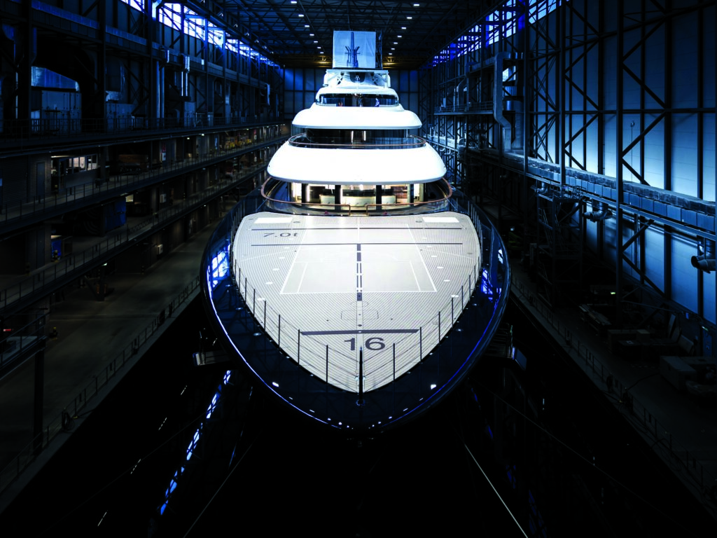
(Image courtesy of Feadship)
Manufacturers are harnessing the potential of the cheaper, clean energy for shipping and aircraft, reports Nick Flaherty
Fuel cells that convert hydrogen into electric power for e-mobility have a chequered past. This has been perceived as high cost, with issues when integrating it into powertrains and supplying hydrogen from pressurised tanks. However, there has been a recent shift to develop the technology for heavy duty e-mobility applications, such as trucks and trains – and now for shipping and aircraft.
The latest systems are being designed as modular assemblies with multiple fuel-cell modules, supported by one set of infrastructure to reduce complexity and component count, and achieve higher power levels. There is also a focus on improving the design of the fuel-cell stacks to reduce the number of cells, which can easily run to 500, to cut costs.
The European Commission approved its fourth Important Project of Common European Interest (IPCEI) for hydrogen technology in May, this time with a focus on transport and mobility, with BMW and Airbus as lead partners.
The Hy2Move project will support research, innovation and the first industrial deployment in the hydrogen value chain in transport with €1.4 bn of state money. This is expected to unlock a further €3.3 bn of private investment in fuel cells for buses, trucks, trains and aircraft, as well as for storage and refuelling stations.
There are 13 projects in Hy2Move for the integration of fuel-cell vehicle platforms for use in buses and trucks, and in the development of high-performance fuel-cell technologies to move ships and locomotives. There is also a focus on improving electric aircraft technology.
(Image courtesy of Hyfindr)
Fuel-cell technology
A single fuel cell is made up of very few parts: two plates (negative anode and positive cathode) to fulfil the structural function, and provide electrical and thermal properties; gaskets to help provide gas seal under operation; gas diffusion layers (GDL) to aid gas distribution and water management within the fuel cell; and a membrane electrode assembly (MEA).
(Image courtesy of Intelligent Energy)
Middle membrane
The MEA is split up into three layers: an anode electrode, a cathode electrode and a middle membrane layer. The electrode layers are generally comprised of a porous material combined with a catalyst, and the electrolyte membrane is made of polymers to provide chemical and mechanical support. It is important that the membrane layer of the MEA is electronically insulating and should only facilitate the transportation of protons through it to the cathode side.
The single fuel-cell parts are compressed to ensure they are sealed and there are no gas leaks. The hydrogen is fed into the anode side and, with the help of the GDLs and plate flow fields, it flows onto the anode side of the MEA. It is here that the hydrogen is catalytically split into protons and electrons, and the protons are conducted through the electrolyte membrane to the cathode side.
The electrons pass along an external circuit (via the anode plate) to the cathode side of the MEA (via the cathode plate), which generates the DC load output of the fuel cell. While this is happening, oxygen from the ambient air is fed into the cathode side of the MEA. Here, oxygen molecules react with the protons transported through the membrane and the external electrons to create water molecules.
Proton-exchange membrane (PEM) fuel cells have higher power densities, lower weight and volume than other fuel cells, such as solid oxide cells, which are used for stationary power. They also have lower running temperatures, allowing for more rapid start-ups and less wear on system components.

(Image courtesy of Feadship)
Fuel-cell stacks
Single fuel cells are stacked on top of one another to create a stack of any number, based on the power requirements of the system. Endplates (positive and negative) surround the base and top of the stack, providing current take-offs and sound structural support.
Fuel-cell stacks are housed within a fuel-cell module, which in turn contain a fuel-cell stack with the required components to operate and manage the generation of power; e.g. control software, electronics, hydrogen valves and fans. Communication between the system and a fuel cell is essential for the ongoing running of the latter and the generation of usable power.
However, a number of other components are required around the stack, called the balance of plant (BoP), of which a key part is the humidifier.
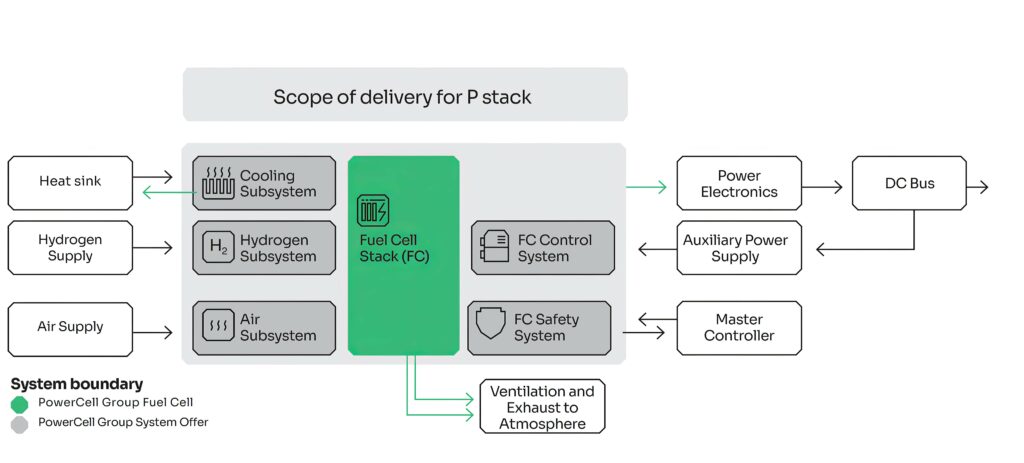
(Image courtesy of Powercell)
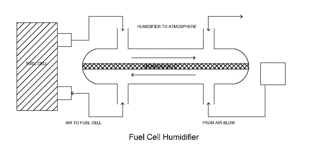
Protective humidifier
A fuel-cell humidifier protects the fuel-cell membranes against drying out. In addition, the humidifier provides humidity by transferring water vapour from the exhaust gases to the intake gases. The gases sent to the fuel cell are humidified to maintain the optimal hydration level of the membrane.
For a PEM fuel cell, water management is important since proton conductivity of the polymer electrolyte membrane, which plays a critical role in determining cell performance, is proportional to the hydration level of the membrane. A variation of relative humidity from 85% to 35% causes a full order-of-magnitude reduction of the protonic conductivity of Nafion, from 0.09 Scm to 0.009 Scm.
Principally, a fuel cell needs to be hydrated using a fuel-cell humidifier. Excess water causes diffusion of the reactant gases towards catalytic layers, which reduces cell performance, along with losses due to concentration, polarisation and mass transportation. For high performance and good proton conductivity, it is essential to maintain optimal water content in the membrane, achieved by feeding humidified reactant gases through a humidifier.
The water produced internally by the oxidant reduction reaction is generally not enough to ensure sufficient hydration of the electrolyte membrane everywhere in the cell. The drying effect of the reactant streams removes this product water from the GDL and leaves the membrane dry, especially at the beginning of the flow field channels.
To compound the problem, while it is desirable to operate the fuel cell at higher temperatures to minimise activation losses, the resulting drying effect becomes more pronounced due to the exponentially increasing nature of the saturation vapour-pressure curve.
A more humidified membrane has a higher protonic conductivity and a longer lifetime, so fuel cells must be integrated with humidifier modules to achieve optimum performance.
A fuel-cell humidifier consists of various parts, differing between models. The conventional humidifier has an input channel for incoming hot gases and an output channel for outgoing cool gases. Based on the type of humidifier selected, a separation membrane, plate or tube will separate the hot and cool gases.
The lifetime of a PEM fuel-cell humidifier is the vital parameter and it depends on its operating parameters and efficiency, with the maximum being 18,000 to 20,000 hours.
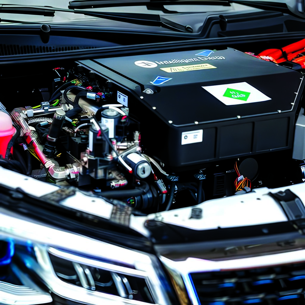
(Image courtesy of Honda)
Automotive engineering
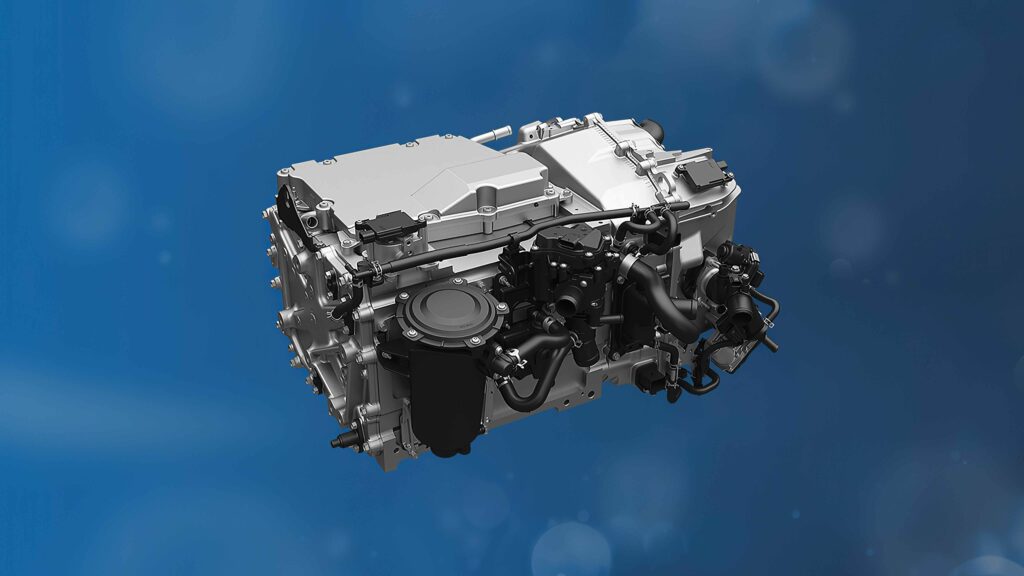
Intelligent Energy has developed a hydrogen fuel cell for passenger vehicles with a heat exchanger that is 30% smaller than current designs. The 157 kW module is the first fuel-cell system created in the shape of an engine to simplify its integration into car designs.
IE-DRIVE is a complete fuel-cell system in the shape of a traditional engine and it is designed to meet the low-bonnet requirements of passenger cars. It includes the fuel-cell stack, electronic control unit, heat exchanger and BoP.
Intelligent Energy’s IE-DRIVE system is designed to give passenger-car manufacturers direct access to a smaller, more powerful turnkey and commercially viable hydrogen fuel cell. It has already been incorporated into a sports utility vehicle (SUV) provided by Changan UK as a demonstration.
The module uses a patented, direct water-injection technology to reduce the size of the heat exchanger to 0.34 m², but it enables cruising at 130 km/h in peak temperatures and a speed of 90 km/h to be achieved when travelling up a long, steep hill. Having a small heat exchanger makes vehicle packaging much easier and benefits fuel-cell vehicle design, particularly in relation to bonnet height and improved driver visibility.
The direct water-injection system has allowed Intelligent Energy to reduce the number of components and bill of materials, removing the need for a humidifier and related parts. Under full-scale, high-volume manufacturing conditions, Intelligent Energy predicts that its IE-DRIVE fuel-cell system will cost about $110 per kW by the end of the decade, making it less expensive than battery vehicles and comparable to ICE.
The fuel cell was developed as part of the ESTHER project in the UK with the Changan R&D Centre, Lyra Electronics and bus maker Alexander Dennis. Changan provided essential support during the project, including the provision of three SUVs to enable fuel-cell testing.
(Image courtesy of Ballard Power Systems)
First hydrogen superyacht
Project 821 is the world’s first hydrogen fuel-cell superyacht. Over the past five years, yacht maker Feadship in the Netherlands has been working on fuel-cell sources for a yacht measuring over 100 m long.
One of the biggest hurdles was how to develop a reasonable way of storing compressed liquid hydrogen below deck at -253 C aboard a luxury yacht. Safely storing it on a vessel requires a double-walled, cryogenic storage tank in a dedicated room. It takes eight to 10 times more space to store hydrogen than its energy equivalent in diesel fuel.
In total, the cryogenic fuel tank that holds 92 m3 (some 4 t) of hydrogen on Project 821, the 16 compact fuel cells, their switchboard connection to the DC electrical grid, and the vent stacks for the escaping water vapour added 4 m to the yacht’s original specification length.
Importantly, the fuel cells developed for Project 821 can use the easier-to-store methanol, a liquid fuel, in ambient conditions. Steam reforms methanol into hydrogen before the electrochemical reaction in the fuel cell. However, even this amount of hydrogen is not enough to provide the power needed for a crossing. Instead, it is used to provide the ancillary power of the yacht.
According to the Yacht Environmental Transparency Index (YETI), 70-78% of a yacht’s total energy use per year is to supply its hotel load, with heating and air conditioning the largest demands.
Project 821 has an efficient waste heat recovery system from the fuel cells to heat everything from the pool to the ambient air temperature and floors in the guest bathrooms. Further savings in the hotel load will come from a Smart AC system connecting sensors to an energy management system.
For longer travels or when pure hydrogen is unavailable, the electricity powering the 3,200 kW ABB pod drives come from MTU generators combusting hydroHVO, a second-generation biofuel that cuts harmful emissions by 90%.
Using hydrogen fuel cells reduces demand for battery power. Project 821 stores 543 kW hours of energy in batteries, compared with Feadship’s first diesel-electric hybrid, the 83.50 m Savannah, which was launched in 2015, and stored 1 MW.
Next year, two long-route Norwegian passenger and car ferries will enter into service using the marine fuel cells developed by PowerCell Group for Project 821. The company is also supplying two 100 kW marine fuel-cell systems to retrofit the The Prince Madog, a research vessel co-owned by Bangor University.
(Image courtesy of Airbus)
Big trucks
Honda and General Motors (GM) in the US have been working on fuel-cell systems for big trucks over the last decade, and have now shown a large, Class 8 truck.
The truck uses a new generation of fuel-cell and system design that has been developed from the ground up over the last eight years to improve energy density and cut costs by two-thirds.
The Honda system uses a solid, polymer membrane and each cell consists of an electrode assembly, where a solid, polymer membrane is sandwiched between a hydrogen electrode and an air electrode. This is combined with bipolar plates that act as separators to form the flow paths for hydrogen, air and coolant. Each cell functions as generation unit and fuel-cell stack, consisting of layers of individual cells. The development team revamped the whole fuel-cell system, starting with the cell structure.
In the previous system, one cell unit consisted of three sheets of separators and two sheets of electrode assembly (MEA). In this generation, the cell structure is simplified to consist of one sheet of separator that welds two plates together and one sheet of electrode assembly (unitised electrode assembly, or UEA) per unit.
A flow path for coolant is formed inside the bipolar plate, while the flow path for hydrogen and air is formed between the bipolar plate and the UEA. This structure enables the cooling of each cell, instead of cooling every two cells adopted for the previous one. Cooling performance was improved by optimising the aspect ratio of the cell, leading to increased durability.
While the previous system required flow-path structures on both the separator and plastic frame of the membrane, the new system consolidates the flow-path structures on the bipolar plate, allowing the plastic frame to have a simpler structure, helping to lower costs.
As coolant flows through the hollow between the two welded plates, the separators require very precise welding. A high-precision laser technology was thus co-developed by Honda and GM to weld the metal plates together.
As the electrode assembly is sandwiched between two bipolar plates to create flow paths for hydrogen and air, the cell sealing is critical. The previous system used silicone rubber moulded onto a special metal plate to ensure sealing performance using the elasticity of the rubber. Now, the system uses a more common metal seal, and the elasticity of the hollow spring structure formed by the two plates is used for sealing. The micro seal is screen-printed for higher sealing performance.

To ensure electrical conductivity, instead of applying gold-plating to the entire surface, a new film formation method was adopted using physical vapour deposition (PVD) coating to deposit carbon on top of a highly corrosion-resistant titanium layer. Coating titanium and carbon before stamping enables continuous processing, improving productivity and cutting costs.
By consolidating the flow-path structures on the separators, it was no longer necessary to form a flow-path structure on the plastic frame of the electrode assembly. Therefore, the precision injection moulding of expensive engineering plastics was replaced with the die-cutting of plastic film as the method to form the frame.
The production process of the electrolyte membrane was also reviewed. By forming the membrane from a liquid material and applying the catalyst at the same time, the base film was no longer required, and the membrane thickness was reduced by 40%, compared with that of the previous systems, cutting costs. Durability was improved by increasing the use of cerium and neutralising side reactants from water electrolysis, which is one of the causes of deterioration of the electrolyte membrane.
All this results in fuel cells with 15% fewer layers without lowering net output. The output per individual cell was increased by optimising the area of the cell’s power-generation section, and the power consumption of the supporting equipment, the BoP, was also cut.
The structure of the electric turbo air compressor was simplified from the previous two-stage compression to one-stage compression by increasing the compressor’s rotation speed by 1.5 times. The humidifier bypass valve was eliminated as the stack became capable of operating at high humidity and the EGR pump was eliminated through the adoption of a new control technology.
When the ambient temperature is low, the water-cooled intercooler warms up the intake air to reduce the amount of water (dew) from the condensation that forms at the inlet of the stack and improves low-temperature start-up performance down to -30 C.
The hydrogen pump was eliminated as the pressure-boost control during startup improved hydrogen-displacement performance. The temperature and water-level sensors were replaced with temperature prediction and water estimation, based on data from other sensors. The pressure-switching valve and secondary regulator were removed by using a chamber and optimising the injector-mounting structure.
Humidity was another area that Honda focused on. The electrolyte membrane that lets hydrogen ions pass through to the air electrode side has the characteristic that a rise in humidity increases its permeability to boost power-generation efficiency. However, if water remains on the power-generation surface, it narrows the airflow path and reduces power-generation efficiency. To maintain the appropriate humidity, it is therefore necessary to adjust the temperature of the cell and carefully control the amount of evaporation of the surrounding water.
The new system estimates the amount of water vapour in the ambient air supplied to the fuel cell using a model-based estimation method, and it realises optimal humidity control based on that model using an electric temperature-control valve and a high-efficiency humidifier. This enables more precise control, lowering the stack temperature to boost humidity and increasing the temperature to lower humidity.
Such precise control enables the system to stabilise the stack’s power generation and boosts durability by preventing the deterioration of the cell by increasing the level of humidification.
The operational Honda Class 8 truck concept is powered by three of the new Honda fuel-cell systems, each at 80 kW. These fuel cells are in mass production at Fuel Cell System Manufacturing, a joint-venture facility with GM in Brownstown, Michigan. The 240 kW fuel-cell system can provide a top speed of 70 mph and a driving range of 400 miles with a high-pressure, 700 bar tank that holds 82 kg of hydrogen, as well as a 120 kWh battery.
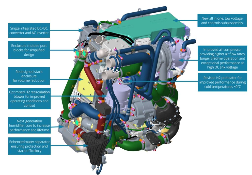
Ballard Power Systems has developed its ninth-generation fuel-cell engine, aimed at heavy-duty applications, such as trucks and construction equipment.
The FCmove-XD engine has a volumetric power density of 0.36 kW/L and a gravimetric power density of 0.48 kW/kg. The scalable, single-stack, 120 kW fuel-cell engine integrates the power controller with the DC/DC converter, air-compressor inverter and power-distribution unit, along with proprietary software controls. This integration is part of a focus on cutting the number of components by 30% to reduce size and boost reliability.
The design allows up to three modules to operate as one system with a single interface, capable of delivering a power output of 360 kW. The engine has a design life of 30,000-plus hours of operation or over one million miles in truck operation at typical duty cycles.
“The power and performance requirements of the highly segmented truck market are particularly demanding due to various use cases, including high vehicle utilisation rates and payload requirements,” says Silvano Pozzi, vice-president of Product Line Management.
“One of the compelling features of FCmove-XD is scalability, based on modularity. We can offer customers efficient integration of 120 kW, 240 kW and 360 kW solutions, dependent on truck class, use case and duty cycle.
“For example, two engines, totalling 240 kW of power output, can be easily installed in the engine compartment of a typical Class 8 heavy-duty truck, enhancing standardisation and redundancy.”
Pozzi points to the collaboration with the maturing supply chain on new BoP component designs and related design costs for integration into a vehicle, as well as investments in certain production tooling to help reduce the cost of assembling the fuel-cell engines.

Aircraft
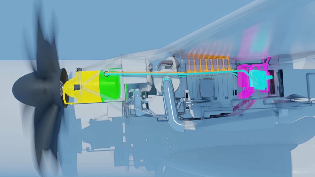
In late 2023, the ZEROe team at Airbus developed a hydrogen-propulsion system for an electric concept aircraft. As well as the hydrogen fuel cells, the system, called an iron pod, contains the electric motors required to spin a propeller, and the units that control and cool them. The 1.2 MW system is a key step towards having a hydrogen-propulsion aircraft in service by 2035.
Extensive testing on the fuel-cell system occurred at E-Aircraft System House (EAS) in Ottobrunn, Germany.
“It was a huge moment for us, because the architecture and design principles of the system are the same as those we will see in the final design,” says Mathias Andriamisaina, head of testing and demonstration on the ZEROe project.
“The complete power channel was run at 1.2 MW – the power we aim to test on our A380 demonstrator.”
The tests particularly examined the way systems interact. “This process is how we learn what changes need to be made to make the technology flightworthy,” says Hauke Peer-Luedders, head of fuel-cell propulsion system for ZEROe.
“We measure how the propulsion system as a whole works by testing the power needed for several different flight phases, such as takeoff, where we are reaching maximum power levels, and cruising, when we use less power but over a longer period of time.”
Testing will continue on this first version of the iron pod throughout 2024. Once completed, the next step for the ZEROe team will be to optimise the size, mass and qualifications of the propulsion system to meet flight specifications. Qualifications include the system’s reaction to vibration, humidity and altitude, among other factors.
Once these optimisations and tests are complete, the fuel-cell propulsion system will be installed on the very first A380 ever produced by Airbus, the MSN001. This will be followed by ground-testing of the systems before the pivotal stage of testing them in flight on the A380, scheduled for 2026.
Looking ahead
The next step for Airbus is to use cryogenic cooling for the hydrogen to support superconducting elements in the fuel cell and the electric motor.
The Cryoprop demonstrator will integrate 2 MW-class, superconducting, electric propulsion systems, cooled by liquid hydrogen via a helium recirculation loop, and developed by Airbus teams in Toulouse, France and in Ottobrunn.
Airbus has been developing superconducting technologies for high-power electric propulsion for several years, culminating in the power-on of an integrated, 500 kW cryogenic propulsion system last year.
The plan is to develop expertise in superconducting cables, motors, cryogenic power electronics and cryogenic cooling systems.
ONLINE PARTNERS


