


")


")

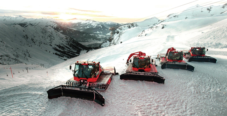
H2D2 snow groomer
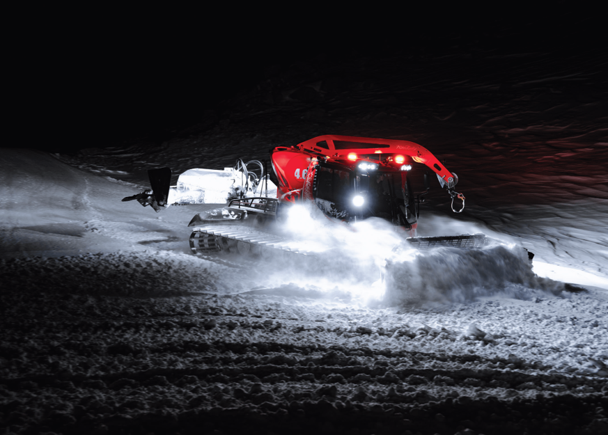
(Image courtesy of PistenBully)
Power on the piste
A unique project plans to electrify the niche market of snow groomers, reports Rory Jackson
More than 300 ski resorts decorate the five mountain ranges of France, and these are home to some vehicles that are quite unlike those found at any other kind of sporting retreat.
One may at first think of snowmobiles, once described to us as “possibly the hardest type of vehicle to electrify” given the icy environments, high vibrations and duty cycles they must be designed to handle – although, as seen in our feature on the Aurora Powertrains eSled in Issue 16 (winter 2022), a few companies are starting to successfully design and commercialise such vehicles to run on batteries rather than diesel.
Snow groomers are arguably less thought of, despite being more central to the running of ski resorts. Also known as ‘trail groomers’ in American English or ‘piste bashers’ in British English, these are large, heavy vehicles, typically powered by diesel engines and running plough-like, hydraulically operated sets of blades, tillers and other snow-shaping equipment off their front ends.
Through the hydraulic equipment running off their diesel engine shafts, these powerful mobile machines are widely used in the maintenance of ski slopes, as well as the erecting of winter sports structures such as half pipes, terrain parks and snow-tube parks, which are highly valued by skiers and snowboarders, not to mention the grooming of cross-country skiing trails, and the clearing or ring-fencing of roads and runways for logistics or medical services to make their way in and out of resort grounds.
Standard snow groomers come with significant drawbacks, however. They typically consume a costly 30-35 litres of diesel per hour. It follows that they produce copious carbon, NOx and other pollutants harmful to resort patrons, not to mention considerable noise. Their high fuel consumption, the wintery environments in which they work and the many moving parts in their diesel powertrains also make for very high maintenance costs when using fleets.
Take all the financial and experiential benefits that could be gained from curing snow groomers of their need for diesel, and group these with the existential threat that climate change poses to the survival of ski resorts or any other industry reliant on snow-capped mountain tops (with average annual snow cover days projected to decline by 50-78% in some ranges over the next 50 years), and one can anticipate great motivation to design an electrified snow groomer.
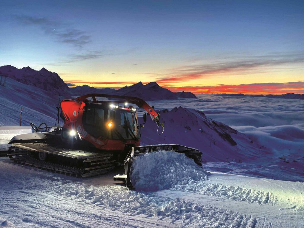
(Image courtesy of PistenBully)
Alliance Française
The H2D2 project is an effort to realise precisely this, funded through the France 2030 plan for strategic green investments, and owned and operated by L’Agence De La Transition Écologique (ADEME), France’s agency for fighting global warming.
The H2D2 snow groomer integrates a hydrogen fuel-cell range extender; H2 gas being the main energy storage medium chosen by the consortium’s engineering contributors.
These include motor manufacturer EREM, public research organisation IFP Energies nouvelles (IFPEN), Kässbohrer and Groupe GCK (Green Corp Konnection) – specifically, GCK Mobility from the group’s mobility division, and GCK Battery from its technology and industry division.
“Many of our organisations had worked together before. GCK and EREM had previously collaborated to make an electric motor for retrofitting passenger cars, such as the Lancia Delta. EREM and IFPEN worked together on that successful motor, which motivated us to discuss the possibility of retrofitting heavy vehicles,” says Misa Milosavljevic, project leader, electric components & systems for mobility at IFPEN.
“Obviously, snow groomers are a small niche market – albeit important to electrify – but the funding grant was given knowing that the powertrain retrofitting kit we’ve developed for use with snow groomers can also be applied very well to buses, trucks and other types of heavy industrial vehicles requiring high power over lengthy travel distances one day.”
Each of these France-based organisations has contributed its expertise to produce what is today a hydrogen-electric snow groomer capable of six to seven hours of operation between refuellings (a targeted runtime to suit the length of a driver’s shift with the vehicle), 15 kph top forward speed, and 320 kW of power output across its treads and blades.
There is up to 84 kW/h of onboard energy in the battery pack and up to 50 kg of H2 gas, stored at 700 bar across three pressure vessel tanks.
As hydrogen gas has a gravimetric energy density of 33.6 kWh/kg, this makes for 1680 kW/h of maximum total energy across the H2 tanks (and the group has a particular shared ambition towards exploring sources of green hydrogen).
The system was created by retrofitting an existing, diesel-powered snow groomer with the FCEV powertrain, both to avoid the project overheads of making a new one from scratch and to demonstrate how existing, familiar equipment could be cost-effectively and labour-efficiently made into something sustainable and zero-carbon as a retrofit solution or an all-new EV and powertrain.
That retrofitted machine is about 9 m long, 3.5 m wide and 3.2 m tall, while weighing about 11 t. Through its electric powertrain and weight distribution, the snow groomer can safely operate on inclines of 45°.
“The group of companies behind this project first started discussions in early 2021, and by the middle of the year the project was officially launched, with all the partnerships, roles and objectives having been defined, and grants from the French government having come in,” says Florent Aussibal, retrofit projects manager at GCK Mobility.
“During 2022 and 2023, we focused on the design and engineering phases of the project, with particular work on assembling the major components, such as the battery pack, the fuel cell and the electric motor, as well as putting them individually through bench testing. Also, in 2023, we integrated the electric propulsion system into the snow groomer and tested it, although not yet with the fuel cell at that time.
“Today, we’re in the final stages of development as we’ve assembled our electric powertrain, including the hydrogen system, integrated it in the snow groomer and completed our first rounds of tests of the complete FCEV system on Groupe GCK’s test circuit near Clermont-Ferrand, with the next round of testing set to take place in the Alps, starting in April 2024.”
(Image courtesy of Groupe GCK)
Retrofitting the 600
The H2D2 snow groomer is a retrofitted and electrified PistenBully 600, which defines several of the physical dimensions described earlier, and the consortium has aimed to keep the size, weight and power the same as on the original to prevent operators or fleet managers needing to get to grips with dramatically different vehicle dimensions or dynamics.
The vehicle is a very popular model in the ski resort industry, making it a logical proving ground for the viability of commercially electrifying such vehicles.
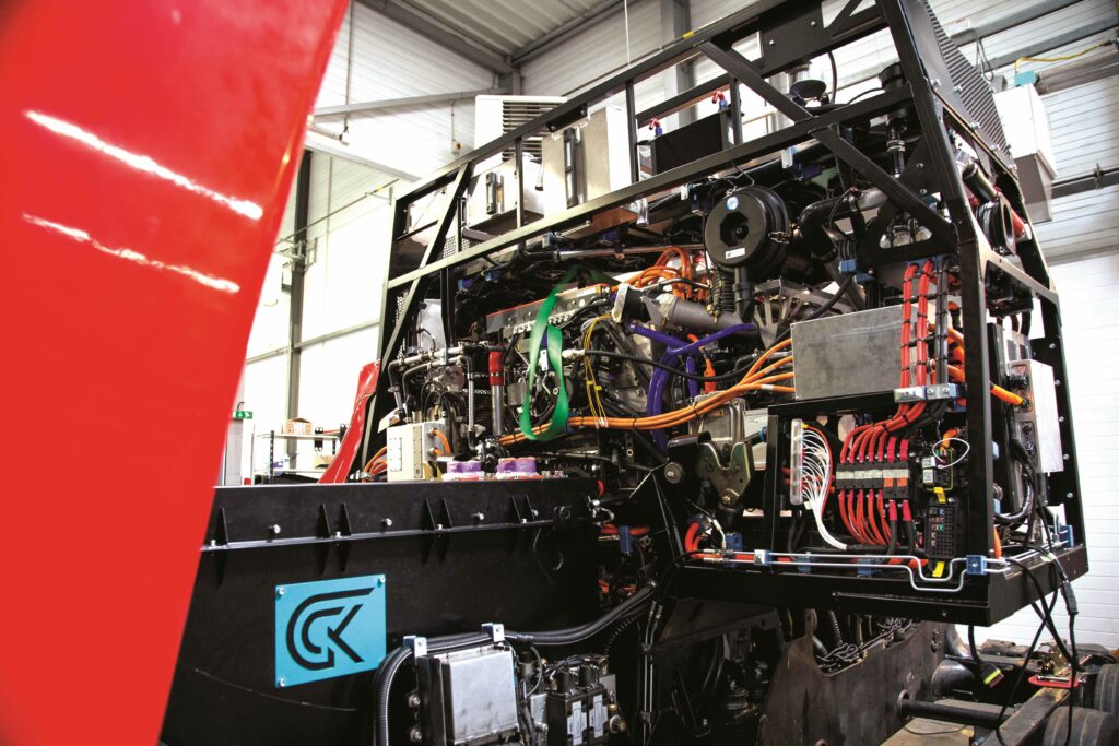
In the rear, where there would normally be a six-cylinder diesel engine, there now sits an electric motor, both to ensure the availability of shaft horsepower to drive the transmission systems for the ground tracks and the snow blade or tiller equipment, and to maintain the system’s weight distribution and low centre of gravity (CoG).
The battery pack is located under the driver’s cabin, thereby contributing to the CoG and weight distribution. Meanwhile, the fuel cell and tanks are installed in a chassis behind the cabin.
Naturally, the inverter is mounted adjacent to the motor, as is a DC/DC converter for stepping up the fuel cell’s low voltage to one high enough for recharging the battery efficiently.
Throughout the cabin and powertrain, cabling and connectors have been judiciously selected to maximise the lifespan of the powertrain against repeated thermal expansions and contractions (as well as weathering caused by moisture freezing, expanding, and melting in the nooks and crannies of part enclosures).
Aussibal explains that thermal management of the various powertrain systems poses the biggest overall challenge, and to that end the battery and the electric motor have been designed with novel cooling systems.
(Image courtesy of Groupe GCK)
Centralised control architecture
Engineering the communications and information transmissions throughout the control network was a considerable challenge, as the team needed to achieve comms performance between each system (and driving response) on a par with the original snow groomer. This meant, for instance, that the acceleration pedal had to achieve the same throttle response from the electric motor as with the diesel engine previously installed.
The vehicle’s data and signal network run on a centralised control architecture, centred around a commercial off-the-shelf (COTS) vehicle control unit (VCU).
“All systems communicate with this VCU. The operator can monitor motor speed, temperature and torque, as well as the battery voltage, current and so on,” Aussibal says. “The VCU will communicate and transmit output signals to the motor for speed, power and torque, based on driver inputs.”
While the VCU hardware is a largely unaltered COTS system, the software is continuously adapted for smooth and error-free communication with the electric powertrain systems, cabin systems and grooming equipment.
Much of the original cabin systems have been kept as they were on the original PistenBully 600. Key changes include the integration of a dedicated tablet system, through which the driver can selectively monitor health and performance parameters across the battery, fuel cell, motor and inverter.
The GCK-FEV fuel cell
(Image courtesy of Groupe GCK)
The fuel cell located behind the cabin has been co-developed between GCK and Aachen-based FEV Group (GCK working in parallel with the latter on high-performance fuel cells for the Dakar Rally through its motorsport arm).
The system is a proton-exchange membrane (PEM) fuel cell. For those unfamiliar with such systems, they consist broadly of a tightly sealed stack of thin, multi-layer membrane electrode assemblies (MEAs), individually separated by bipolar plates (BPPs).
Each MEA generally consists of a central proton-exchange membrane (typically made of Nafion or a similarly semi-permeable material), sandwiched on either side by a catalyst layer – often platinum, carbon or a mixture of the two – and outside of the catalyst layers are gas diffusion electrode layers: one an anode layer, the other of cathode.
H2 and O2 (the latter typically drawn from ambient air using a fan) are pumped into the stack, with the H2 fuel flowing into the anode sides of the MEAs, and the O2 reactant flowing into the cathode sides, with the BPPs constructed and shaped to optimise the flow channels of either gas.
The catalyst layers in the anode side induce hydrogen ions to split from the H2 molecules, pass through the PEM and bond with the O2 molecules to form water vapour, which passes out of the MEA stack with unused air as exhaust (why PEM fuel cells are not zero-emission, but zero-carbon, technically).
When the hydrogen ions split and pass through the MEA, each releases an electron, which travels along and is (ideally) conducted out of the MEA as direct current, producing power through the cable running from the stack. The energy efficiency of modern PEM fuel cells – the proportion of electrons drawn from the H2 as electricity, as opposed to being released as heat – tends to hover around 50%.
While material and architectural specifics inside the H2D2’s stack are confidential, the fuel-cell system in the snow groomer (comprising the MEA stack, its control electronics and power electronics) measures about 1 m tall, 1 m wide and 1.5 m long, while weighing 400 kg and producing 175 kW net power output.
A liquid-cooling circuit runs about the stack, given not only the heat dissipation requirements but also the potential for redistributing the fuel cell’s heat around the snow groomer to prevent excessively cold conditions along the powertrain and elsewhere.
MEAs inherently produce current at a lower voltage than is ideal for recharging HV batteries. To that end, a DC/DC is installed at the stack’s outlet, which steps up its voltage output from 370 V to 500 V, compatible with the 800 V battery. A dedicated fuel-cell ECU monitors a variety of temperature, electrical, gas flow and pressure sensors to track the health and performance of the stack – that tracking is also available via the driver’s display.
“Going forwards, we will be focusing on and studying how well the cooling system performs, as that is critical for the health and thermal efficiency of the fuel cell. That’s the main piece of a larger action plan to optimise and mature the fuel cell over time, with testing plans aimed generally at running it as much as we can to uncover issues that need fixing,” Aussibal notes.
(Image courtesy of Groupe GCK)
Energy storage and recuperation
Fuel cells typically produce power and voltage at varying rates, so a DC/DC as well as a small battery are typically installed downstream to stabilise the power output. The consortium realised the battery pack in the snow groomer would need to fit in a space that is 1.4 m wide, 0.5 m long and 80 cm tall, and it has opted for one that fits these dimensions and weighs about 950 kg.
“It has a capacity of 144 Ah, and while the original project target was 84 kW/h of battery energy onboard, we provide just under 90 kW/h of useable energy storage. Technically, the pack’s actual maximum energy storage is higher, but we recommend against using all this as it’s bad for battery lifespans to repeatedly run SoC down to 0%,” says GCK Battery project manager Herve Santiano.
One may ask: if the weight of the energy system can be minimised by using hydrogen gas as a low gravimetric energy density storage system, why has the consortium designed the snow groomer with this (seemingly) unnecessarily heavy battery?
Two reasons come from the fact that traditional snow groomers are expected to be able to handle very steep gradients due to their low CoG and large contact area. Having a large and heavy battery pack under the cabin helps keep that low CoG and a wide, snug contact with the ground.
While some snow groomers use cables and winches to tether themselves to the upper parts of slopes to prevent free-falling, the electrified snow groomer has the added advantage of regenerative braking.
“If the snow groomer is moving down a 45° slope, and it happens to be a long slope, we must have a large and open bank of electrical energy storage, such that the regenerative braking has somewhere to put that recovered energy. We calculated the best way to maximise the autonomy of the vehicle is to have those 50 kg of H2 for powering travel up difficult uphill slopes, and a pack with space for at least 80 kW/h of recovered energy,” says Santiano.
Lastly, having a large battery makes for a useful source of backup energy if the fuel cell suffers a fault mid-operation, so the driver can return for maintenance and repair on battery energy alone.
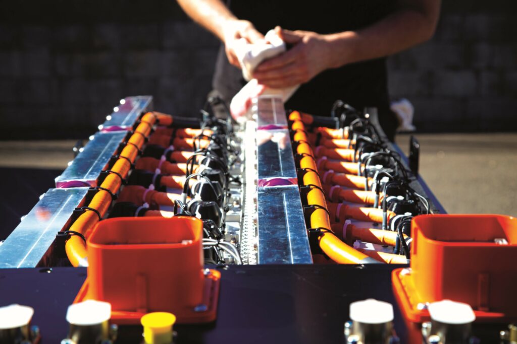
(Image courtesy of IFPEN)
Immersion-cooled cells
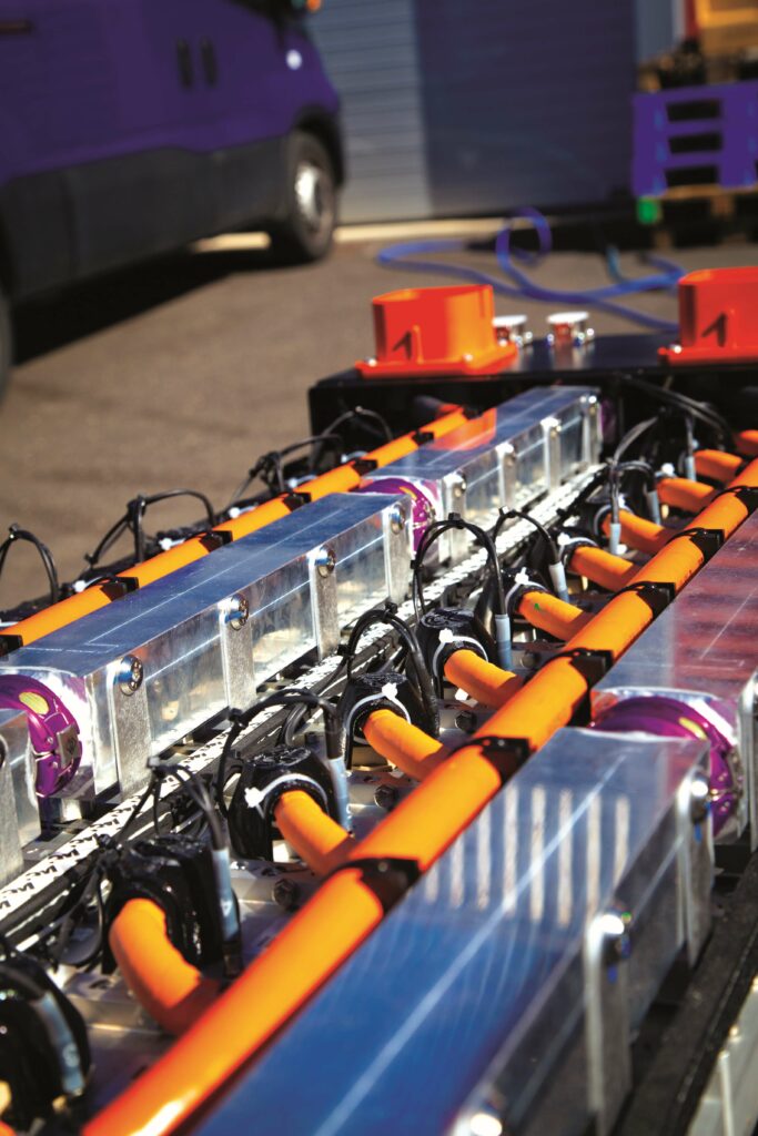
To achieve the energy density needed for a pack of at least 80 kW/h onboard, GCK Battery chose cylindrical NMC 21700 cells, and to aid the power efficiency needed for fast recharging of the pack (either by regenerative braking down slopes or via the fuel cell), an immersion-cooling system has been engineered to enhance the battery’s thermal stability.
“We wanted cylindrical cells so that the modules and pack could integrate our immersion-cooling system; pouch or prismatic cells would not have functioned so well in our dielectric oil,” Santiano says.
“The 21700 cell is the most common and standard type, so it made the most sense to pick that one. We also found NMC to be the most energy-dense of the commercially available cathode chemistries, and we use a nickel-rich cathode – NMC 811, specifically – to maximise that energy density. We can’t go too much into the design of the module, but I can tell you they’re constructed in our automated facilities and connected using automatic resistance welding.”
Each module is a 12s16p system enclosed in a housing that is IP68-rated for protection against dust and water ingress, while being IP2X-rated against penetration by solid foreign objects of 12.5 mm diameter or greater. The housing has also achieved UN ECE R100 certification for use in road vehicles.
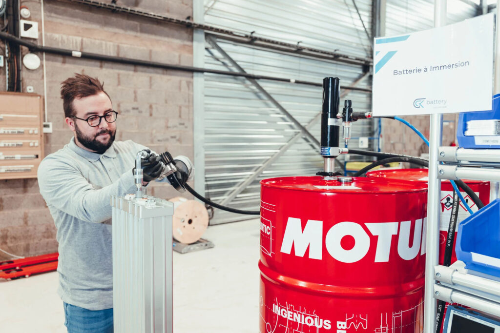
Immersion cooling uses a bath of oil that surrounds every exposed part of every cell and flows through the modules (at an undisclosed flow rate, but significantly lower than in typical water-glycol heat-extraction systems). The oil is a dielectric fluid, blended and engineered by GCK Battery through close collaboration with Motul to achieve a few critical performance characteristics.
“The first characteristic is that it must be electrically insulative, otherwise it will represent a short-circuiting hazard, and it must have a high coefficient of thermal conductivity, oriented around keeping the cells at their optimal 20-25 C window for recharging and discharging, and moreover preventing extremes of temperature that will decrease their lifespan,” Santiano says.
“The oil needs to have a very high flashpoint, as stable performance depends on it always being a liquid and never any other state of matter. A pump sits outside the battery for circulating the oil, and a radiator and fan are installed outside the vehicle chassis – typically out of the way, above the fuel cell – to cool the oil as it flows outside of the pack.”
As to the flow rate of oil through the modules, Santiano says the oil must not move too quickly as effective heat extraction requires some prolonged exposure between the oil and the walls of the cells, and considerable CFD simulation went into studying the ideal oil-flow dynamics and flux for optimising thermal transfer.
The pack has been designed for C-Rates up to 10 in continuous charging and discharging, which immersion cooling is critical towards. It is also valued in preventing fire propagation if a cell goes into thermal runaway.
GCK Battery has run C-Rate tests of its immersion-cooled 12s16p module (one without any flow or radiator) against two other types: one with a single, standard cooling plate and one with dual cooling plates (both were 12s24p systems with higher power throughput than the immersion-cooled module for the same C-Rate).
While the three performed similarly at C-Rates of 1 to 2, considerable thermal differentials emerge exponentially as they were charged at higher rates. At a C-Rate of 8, the immersion-cooled module held at 50 C, while the dual-plate module reached 106 C and the single-plate hit 163 C. At a C-Rate of 10, the immersion-cooled system reached a maintainable 65 C, and the dual-plate unit went up to 140 C. The mono-plate product had surpassed 200 C at a C-Rate of about 8.4, and could not be safely run up to the target C-Rate of 10.
(Image courtesy of IFPEN)
Battery management
The first function of the BMS is to monitor and prevent abuse conditions such as over-temperature conditions, overcurrents, short circuits and so on. It also constantly calculates the SoC, state of health (SoH) and C-Rate of the pack, such that all this information and its subcategory parameters can be reported to the driver in real time.
“The BMS connects to a PDU [power distribution unit] outside the pack. The PDU is a box composed of many electromechanical components, allowing the control, and cutting off, of power from the pack to the inverter and motor when necessary,” Santiano says.
“We install dual PDUs in the snow groomer, and we also split the pack into two halves of modules, so that if there’s a problem with one half we can still run on the other to drive to a safe place to diagnose the problem.”
Hence, the BMS executes and automates safety functions, such as closing the contactors to the pack and controlling the flow rate of dielectric oil.
Electric motor development
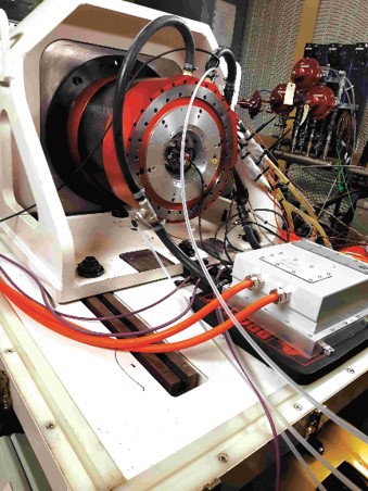
(Image courtesy of IFPEN)
Developing a powertrain that can satisfy both the hydraulic and traction needs of the snow groomer brought considerable specific requirements in terms of the compactness (diameter and length), continuous performance, and cost that the motor and inverter need to satisfy.
At first, the project partners explored COTS options for their electric drive systems, but could not find a motor that reasonably matched the performance and physical parameters targeted. That led to the decision to develop a new e-motor that would match the specifications.
“For us, this was a good thing, as it meant the project represented an opportunity to work towards what we’d like to be a range of efficient e-motors from 30 kW [<60 V] to over 300 kW [800 V], all with scaled versions of the same active parts – stators, rotors and so on,” recounted Adrien Maier, project engineer at EREM.
Meanwhile, the consortium identified a three-phase inverter solution that could ensure minimum performance expectations in the packaging constraints required. This is a 15 kg unit supplied by Punch Powertrain, measuring 328 x 298 x 134 mm and running on silicon carbide transistors.
The powertrain development process started in Simcenter Amesim, Siemens’ vehicle system-level simulation software, first using the initial state of the pre-retrofit snow groomer with its diesel engine to set a series of references, and then using the snow groomer’s finalised architecture to define the specification for each powertrain system and component.
This work was first performed by GCK Mobility, with tests and data acquisition on the initial vehicle, and then by IFPEN for further simulation and definition. Those simulations were used to set targets for the components to be developed, as well as to model for the optimal levels of energy management in the EV. Further industrial, environmental and cost constraints were added as inputs to design optimisations for the electric motor.
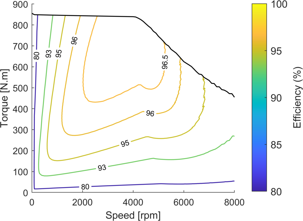
Critical targets for the motor were that it could fit into a space of 390 mm in diameter by 360 mm in length, while providing 320 kW of shaft power and 850 Nm of torque, as well as running at speeds up to 8000 rpm. Additionally, the motor and inverter were to have a collective weight of less than 200 kg.
Further key requirements were that the powertrain needed to be able to run off a 700-825 V DC power supply (per the battery bus), and safely deliver its performance targets in ambient temperatures, ranging from -25 C to 50 C, while also functioning at altitudes of up to 4000 m.
This latter quality poses a safety challenge to higher-voltage powertrains due to the greater risk of partial discharge, a dielectric phenomenon in which some localised portion of insulation in a HV system environment is electrically stressed to the point that it breaks down. At high altitudes, the low air density enables air particles to travel longer distances before colliding with other particles, meaning they accelerate for longer periods and collide with much more kinetic energy than at lower altitudes with higher air densities.
This facilitates higher rates of ionisation than at low altitudes, and those higher rates of ionisation directly lead to higher rates at which conductive paths can form across air gaps inside HV wire harnesses. More conductive paths mean more localised electrical stresses, resulting in more insulation ageing and partial discharges, making electrical safety a huge point of concern for the stator design.
Lastly, the powertrain’s power efficiency was important for meeting targets on maximising the vehicle’s operating time, and thus limit the rate at which the battery cells and H2 tanks would be drained during operations.
Subsequent development of the motor was predominantly undertaken by aforementioned project partners IFPEN and EREM, with their first feasibility investigations starting in early 2021.
“We took significant design influence from the 400 V, 147 kW e-motor previously developed for the Lancia Delta, although a lot of work was needed to scale it up several times over to be big enough for the snow groomer,” Maier says.
From late 2021, until the design freeze in March 2022, IFPEN focused on active part optimisations, as well as material and cooling system evaluations, while EREM concentrated on mechanical assembly designs, and evaluations of production and assembly methods.
“Fortunately, EREM’s stator-winding research led to a satisfactory solution to the partial discharge problem, but it is important to note this aspect is insufficiently covered for full-scale,
high-power motors at the scientific level today, and required a big effort in the design phase from EREM,” Milosavljevic says.
EREM went on to develop the required tooling and produce the complete set of parts before assembling two initial motor prototypes, which were delivered in November 2022 for testing and vehicle integration. In parallel, EREM purchased the aforementioned inverters and received them in July 2022.
The prototyped powertrain was validated at IFPEN, with some help from the inverter supplier (particularly in adapting the inverter software to the motor). Validation was executed in multiple phases by order of priority. The first release of the powertrain in February 2023 brought the opportunity to use it in the slow groomer for the first time, with the final release following in October 2023.
The powertrain is now operational in the snow groomer prototype, and it has also been integrated into another vehicle for testing and validation in harsh environments (with particular attention being paid to its vibration and very high temperature performances).
(Image courtesy of PistenBully)
Permanent magnet-assisted synchronous reluctance motor
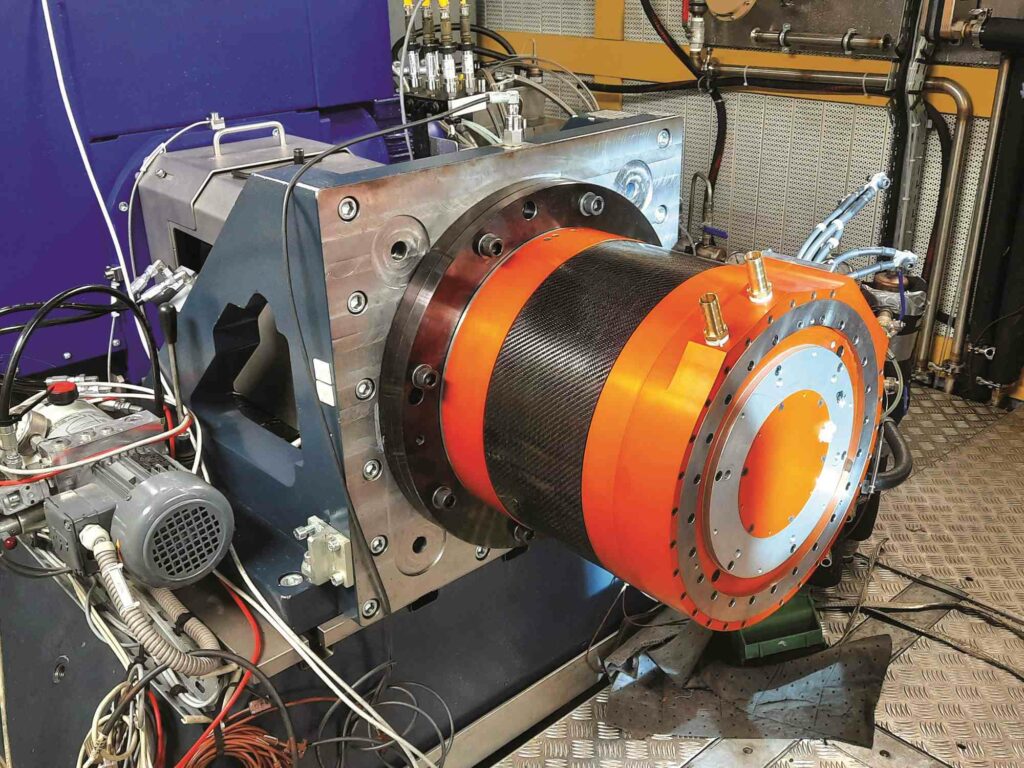
In addition to fulfilling the peak power, speed and torque targets discussed above, the snow groomer’s motor is a radial-flux machine, measuring 360 x 390 mm and weighing 170 kg. Such are its design and optimisation that it produces about 760 Nm of continuous torque from 415 ARMS (while running under test conditions consisting of a 700 V supply, a 500 rpm shaft speed and a 25 C ambient environment).
The system’s peak torque output is 870 Nm, and through testing, the company found that so long as the liquid-coolant circuit functions well in cooling the stator, the motor can be run at low shaft speeds to continuously maintain 77% (675 Nm) to 86% (750 Nm) of the peak torque value.
“Our test results show a significant difference from existing solutions on the market, which typically present continuous torque at 50% or 60% of the max torque value, while our solution keeps a competitive level of compactness in its physical dimensions and simplicity in its cooling design, but also achieves continuous torque of around 80% of our maximum torque capability,” Milosavljevic adds.
Through their joint research, the project partners eventually deemed the permanent magnet assisted synchronous reluctance (PMSR) topology as the best option for designing a motor capable of reaching high performance levels with the minimum of environmental impacts, costs and supply risks in its manufacturing.
The rotor was designed and optimised by IFPEN through a multi-physics, multi-criteria workflow (covering motor geometry, electromagnetics, mechanical design and thermal performance), resulting in a patented design for the rotor laminations.
A key benefit of the PMSR topology (and a key point of focus with respect to the rotor) was that its rotor uses electrical steel to produce over 60% of its torque, with the permanent magnets only assisting in the remaining 40%; that reduces the size of the inverter needed, the quantity of magnets needed per unit, and enables constant power performance up to high speeds.
While the topology requires some elaborate models and algorithms for PWM control to ensure optimal performance, limiting the choices of COTS inverters that can work, the H2D2 project was fortunate enough to still find a suitable inverter.
The resulting rotor design uses seven small magnets per pole, each magnet being identical to optimise and simplify both the assembly process and supply orders. The project partners note that only three part references (the magnet, lamination and shaft) need to be accounted for in the rotor. Overall, the rotor features four pole pairs, while the stator is designed with 48 slots, as well as a distributed, three-phase winding, chosen to reduce the losses in the rotor.
These active parts of the electric motor were developed via an algorithmic optimisation process, designed and honed by IFPEN. In this approach, the company’s proprietary algorithms first use input variables to generate response surfaces, and then the stator and rotor geometries are optimised using the response surfaces to identify the overall optimum motor design.
“This methodology minimises the computation time needed for realising the optimisation, and the exploration and optimisation tool at the heart of our approach integrates its own automatic rotor, stator and magnet geometry generator, which is managed by the mathematical layer,” Milosavljevic explains.
“This tool has proven very handy for exploring the best geometries for a given set of specifications and constraints, as well as for finely optimising the complete geometry of any active motor part under particular mechanical, thermal, industrial and system constraints – including those imposed from the vehicle, the inverter, the battery, the fuel cell, and so on.”

Motor cooling
Additionally, the motor uses a cooling system jointly-patented in 2020 by EREM and IFPEN from a previous joint project, having been successfully adapted to the H2D2 powertrain.
The thermal management approach is optimised around a simple, water-glycol cooling circuit with a cost-efficient potting of the stator coil to enable consistent high performance (particularly consistent torque) with reduced heat loss.
As described in the patent, the stator cooling circuit consists of tubes that pass longitudinally through the stator body, and through the potting material about the coil heads. Those tubes are typically connected by channels located in the motor flanges, resulting in a serpentine form for the cooling circuit around the stator and coil heads.
“We also chose materials for the mechanical parts that would maximise thermal conductivity, to extract heat from the rotor and stator as fast as possible. Having the coolant in close contact with that material is really important,” Maier says.
EREM developed a unique method for stacking the rotor laminations and inserting the magnets, which was validated for the first time on this motor. Maier says optimising the methods and tooling for rotor construction has been one of the biggest challenges to solve in the project.
“We stack the laminations one by one, and then we compress them, install the permanent magnets, and lastly add the thermal potting resins. The stator construction is analogous, starting with stacking and then compressing the steel laminations before inserting the copper and layering on the thermally conductive resin,” he says.
After defining the active parts of the motor, the virtual validation process then made use of ANSYS to analyse the designs for mechanical and thermal regulatory compliance, after which IFPEN proceeded to produce production drawings for the motor components to be prototyped.
Motor testing

Systematic tests of all key motor components were performed, up to the point of validating the motor via in-vehicle trials.
For instance, the choice of magnet model (being critical to the motor’s performance parameters, as well as one of the first components that the consortium needed to buy) was tested at IFPEN, analysed in a histogram and compared against the specifications in its algorithm-derived drawings.
“IFPEN used a rotor test bench to measure the air-gap induction generated from the assembled magnets within the rotor,” Milosavljevic says.
“Starting with those results, we confirmed key predictions we’d gained during performance simulations from the design phase. Then the stator winding realised at EREM was tested for insulation, resistance values and resistance equilibrium between phases. Those results were compared as early as possible with design-phase predictions done by IFPEN.”
The complete rotor assembly has been trialled successfully in IFPEN’s endurance and fatigue testing cell, with the goal of validating the result of the entire rotor development and manufacturing process through exhaustive high-temperature speed cycling (from 0 rpm to its 8000 rpm maximum) featuring overspeeds.
IFPEN notes that getting a passing grade for the rotor’s manufacturing quality from such tests was vital before going on to assemble the complete motor.
“While that 8000 rpm is higher than what the snow groomer needs, it’s important for us to design the motor to run at such speeds for future use in buses and trucks, where their transmissions are designed for running off higher shaft speeds than the snow groomer’s is,” Milosavljevic notes.
The motor’s housing is IP55-rated and built from an aircraft-grade aluminium, with two deep-groove ball bearings (one at the front and one at the back) that are fully sealed, have preloaded springs and are designed for a lifetime, greased operating temperature range of -40 C to 180 C.
The completed motor was verified in high-voltage insulation tests, surge tests, waterproofing tests and more, before going into a full torque and power-test cell with the inverter, where the complete mapping of the motor and inverter performances was performed, through peak and continuous performance conditions.
Once the complete powertrain was validated, it was integrated into the snow groomer, and tested in functional and performance procedures by GCK Mobility. Results thus far indicate a peak efficiency of 95.9% across the installed, finished powertrain with motor and inverter combined.
Future
In addition to now running tests in the French Alps, the project partners are moving towards homologation (certification) of the H2D2 snow groomer by the French authorities.
The consortium aims to commence the full commercialisation and supply of units of the snow groomer as a retrofit kit in the beginning of 2025, so extensive testing in real-world ski-slope conditions is to continue throughout this year, with final modifications and adjustments by Q1 2025.
Adaptations of the kit for use in a broader array of heavy commercial vehicles can be expected in the years ahead.
Meanwhile, the group has a ready market of hundreds of ski slopes in France, which will want its snow groomer fleets electrified. One can expect it to cast its eyes to overseas markets once regulating bodies across Europe, the Americas and Asia provide pathways for electric snow groomers and other equipment to be safety-rated for use on winter sporting courses.
Key vehicle specifications and suppliers
H2D2 snow groomer
Retrofitted PistenBully 600
Hydrogen-electric
PEM fuel-cell range extender
NMC 21700 cylindrical battery cells
SiC inverter
PMSR motor
Dimensions: 9 m x 3.5 m x 3.2 m (excluding implements)
Weight: 11 t
Maximum speed: 15 kph
Maximum power: 320 kW
Maximum energy storage: 90 kWh approx. in battery pack, 50 kg (1680 kWh estimated) in hydrogen tanks
Maximum electric powertrain efficiency: 95.9%
Maximum incline in operations: 45°
Original snow groomer vehicle: Kässbohrer
Powertrain assembly and integration: GCK Mobility
Powertrain modelling software: Siemens
Powertrain modelling software: ANSYS
Powertrain modelling software: IFPEN
Fuel cell development: GCK Mobility & FEV Group
Battery modules and packs: GCK Battery
Battery immersion cooling system: GCK Battery
Battery immersion cooling system: Motul
Electric motor development and production: EREM
Electric motor active parts development and experimental validation: IFPEN
Inverter: Punch Powertrain
ONLINE PARTNERS


