


")


")


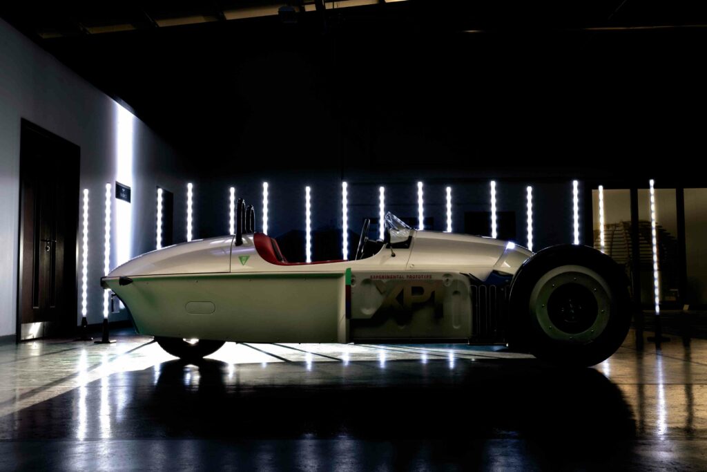
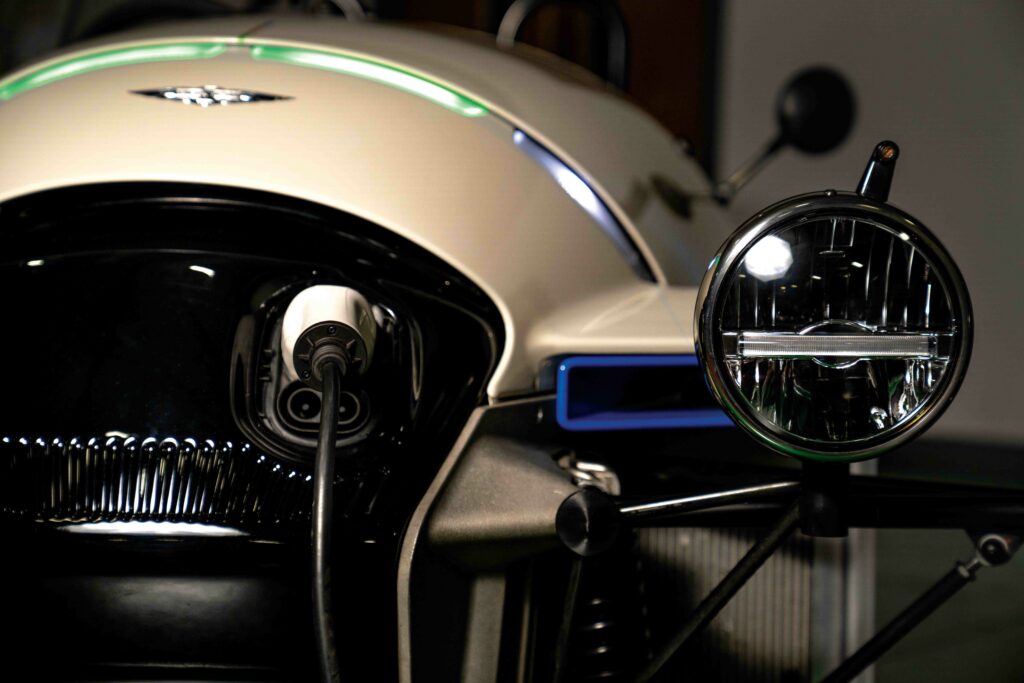
Fellten Morgan XP-1
(Images courtesy of Fellten)
The power of three
Reinventing its classic 3 Wheeler for the modern world, Morgan has chosen Fellten to electrify the XP-1 prototype, reports Rory Jackson
While the Morgan Motor Company has long been known for such unique practices as the handcrafting of its exclusive production runs, iconic car designs that include its classic 3 Wheeler roadster configuration (and its successor, the Super 3) and the use of wood in construction, in more recent years it has grabbed headlines for committing itself to the new age of electrification.
The fully-electric Morgan XP-1 is a love letter to the British company’s aforementioned three-wheeled creation, but as our seasoned readers will know, the process of electrifying or resto-modding a beloved automotive icon is fraught with myriad ways in which one can ruin everything that enthusiasts loved about its fuel-burning predecessor. Maintaining the 3 Wheeler’s unusual appearance in the XP-1 is one thing; recapturing the dynamism and fun of driving it with an electric powertrain is another entirely.
The challenge of this latter hurdle may be the biggest reason for Morgan choosing to partner primarily with Fellten for its electrification needs. Headquartered in Bristol, UK, Fellten was founded about six years ago by now-CEO Chris Hazell and now-CTO Alex Dawood, who met not long before through a shared passion for converting iconic cars into EVs, which culminated in their creation of three stunt cars for the Elekron show in Macau, China.
At the time, the pair were veritably the only ones converting internal combustion engine (ICE) cars into EVs using 400 V systems, so they rapidly gained interest and customers, soon turning their attention to a long-term business model of manufacturing plug-and-play conversion systems for popular car models, including Porsches, Classic Minis and Land Rover Defenders.
Today, Fellten designs and produces these systems, supplying them to trade specialists around the world, who install them for their end-customers.
These systems are intended to be simple enough for any mechanical engineer with at least a two-day electrical safety course to install (the term ‘kits’ is avoided due to being reductive, and implying a collection of parts that specialists must assemble and make work together), although Fellten also provides hefty training for the correct handling and integration of high-voltage battery packs, as well as other key powertrain components.
A unique point of Fellten’s systems is that they are often created through partnerships with the pertinent manufacturer responsible for each car brand and designed to be fully reversible, allowing Fellten-converted vehicles to be converted back into fuel cars, or further modified to use alternate, low- or zero-emission powertrains with minimum complications.
Perhaps most important to motor enthusiasts and Morgan is that Fellten closely tests, and hence prioritises, the weight distribution and balance of each car to recreate as faithfully as possible how it felt to drive its original version (while increasing performance where possible).
In addition to these qualities, Fellten has supplied the XP-1’s battery pack and charging system, along with the associated thermal and battery management system (BMS).
“When Morgan first approached us, around early January 2023, they already knew they didn’t want to make the battery pack in-house. They didn’t have high-voltage training, they didn’t have dedicated build rooms or equipment for safely working with battery components, and they had already firmly decided that they wanted to maintain the original chassis design,” Hazell recounts.
“All EV parts had to bolt onto the original chassis, because so much of it was made by an outsourced company; hence Morgan had no interest in going through a full CAD redesign of the chassis for what would in theory be a one-off prototype.”
That chassis was, as Hazell puts it, extremely tight. “I don’t think it could have been a tighter fit and still have been a feasible conversion. Fortunately, they still had complete CAD files on every single component, so we could simulate every section and process virtually before we ever set foot in a room with the vehicle.”
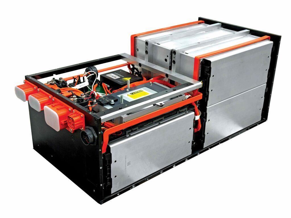
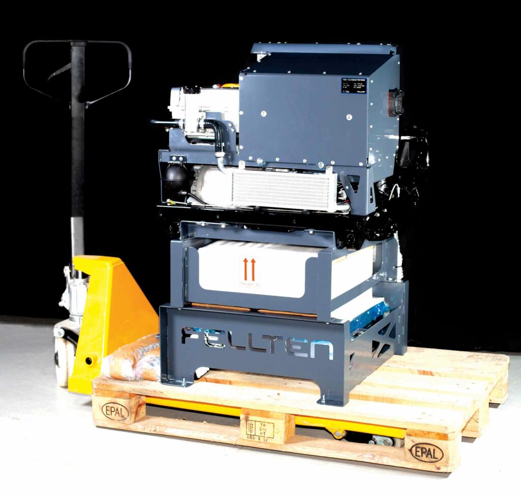
The battery pack itself was developed for Morgan from pre-existing Fellten intellectual property (IP): a 33 kWh pack designed around VDA 355 modules from DFD Energy, battery management from Orion, and a rapid-charging combined charging system (CCS), contactor, and integrated high-voltage junction systems to achieve simplicity and cleanliness of installation.
“For installation, they basically plugged in the inverter, the CCS module and the charging connector, along with two fittings for the battery cooling plates – one in, one out – and that was it,” Hazell summarises.
Vertical integration
The design of the pack is based on Fellten’s Universal Battery Pack, typically 55 kWh. Key takeaways applied in the 33 kWh pack include a distinctly vertical arrangement of the battery modules and structural liquid-cooling plates, as well as a standardised BMS configuration.
“Really, the heritage of the Morgan pack’s technical qualities goes back to a kit we produced for the Porsche 911,” Hazell recounts.
“That was when we started using the VDA 355 module and quickly realised that running the modules flat was really problematic. The classic Porsche 911 doesn’t have floor space conducive to stacking modules horizontally up and up, because attempting that means you need to have floating sections, and it then gets incredibly difficult to link the busbars to have multiple coolant links.”
After confirming the cells and modules could be mounted on their sides and oriented vertically, Fellten developed a liquid-cooling plate, cut 16 mm thick from aluminium billet, that could double as a structural member. As well as having coolant channels running through it, the plates were made with holes through which the modules could be bolted.
“The plates then get bolted top and bottom, and at the sides where possible, to the steel, structural walls of the pack. With the modules bolted firmly to the plates, and the plates fastened securely to the housing, the whole pack becomes incredibly rigid,” Hazell says.
“Since using the cooling plate as a structural member has such a huge benefit, we adapted the configuration into our Universal Battery Pack, and then into the 33 kWh design that is being used for the Morgan project.”
Thermal management
Hazell notes, however, that the original Porsche kit’s pack contained coolant that flowed in and out of the plates, making for a largely self-contained system with just two coolant access outlets. When transitioning the architecture to its 55 kWh standard product, Fellten moved away from storing coolant within the pack, placing it and its ancillaries externally.
“That’s visible in the XP-1 integration also,” he says. “On the bottom of the cooling plate there are five holes: the centremost one functions as a bleed hole, running to the top of the plate to pull out any air that’s trapped up at the top. As the coolant enters at the bottom, there’s a risk of air lock at the top unless the air up there can be drawn down and out of the plate.”
Of the remaining four holes per plate, two function as coolant inlets and the other two as outlets. This dual, inlet-outlet approach helps to maximise the volumetric coolant flow, as the plate’s 16 mm thickness (being a thin span for a cooling plate) limits the channel width and hence the top flow rate per channel.
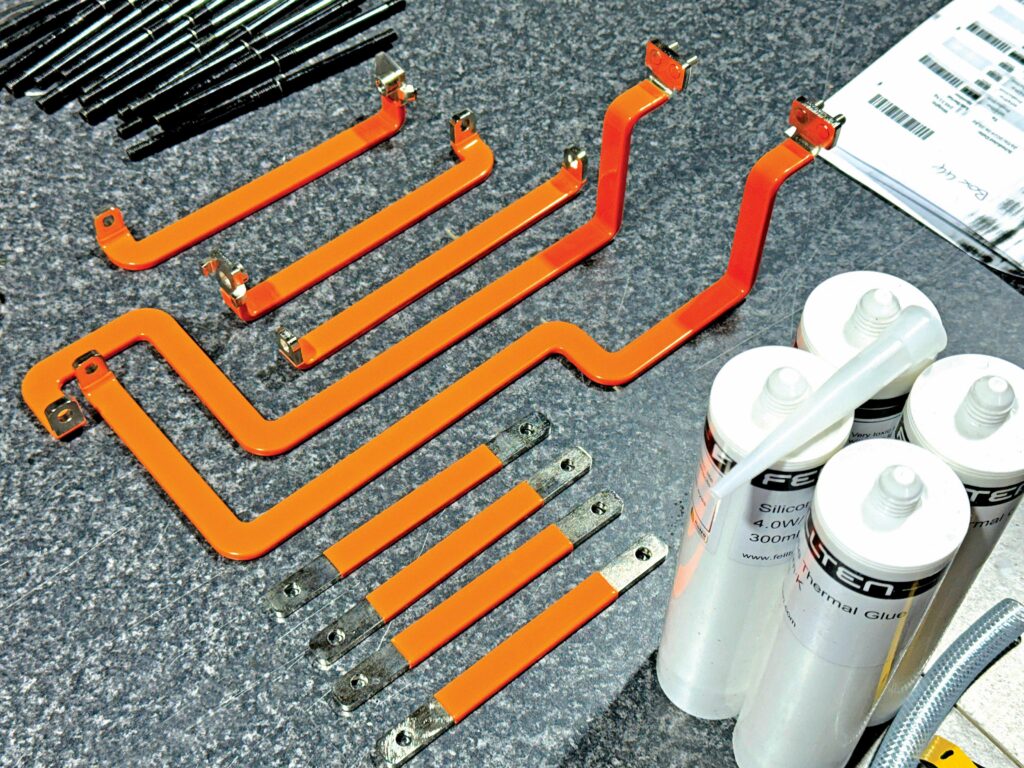
To facilitate this, Fellten has developed a specialised, coolant line fitting with integrated O-rings for pushing up into (and then bolting into) the bottom of the plate. As Hazell explains: “The benefit of this system, which is similar to what GM and Vauxhall have done with their packs, is that it’s an external fitting, so you can’t get a coolant leak internal to the pack through a pipe or tubing malfunction, because everything’s pushing and bolting on from the outside.
“That’s one of the biggest risk factors we came across while doing failure mode and effects analysis: in our opinion, the biggest risk towards failure of a battery pack is coolant leakage, because it completely destroys the modules. It can cause dead shorts and a huge number of other issues.”
While a larger producer of battery packs might be tempted to invest billions into studying the probability of a coolant leak, and the breadth of quality control options available for stopping such an event from ever happening, Fellten’s strategy as a lower-volume manufacturer has been to move the source of the issue from the internals to the outside of the pack.
To ensure effective conduction of heat between the modules and coolant plates, to cool or heat the packs depending on the effect of the surrounding environment, Fellten applies a specialised, thermal paste, glue or pad. Glue is used in the case of the Morgan pack, as many pastes come with a certain viscosity and would drip downwards when applied into Fellten’s vertically-oriented modules, although thermal pads and some caulk gun-applied pastes remain an option for future builds.
“We’ve gone for a glue with a 4 U temperature-transfer capability. Most OEMs go for 2 U, but we’ve opted for a more expensive substance to be sure we stay ahead of EVs’ and powertrains’ thermal requirements,” Hazell notes.
“Although we call it a cooling system, in most of our system arrangements we will actually scavenge the motor heat to warm the battery pack through a heat exchanger – the Morgan XP-1 doesn’t run that, but our other builds do.
“We’ve taken significant inspiration from the pre-2017 Tesla Model 3’s heat-recirculation system and reformatted it for this conversion-aftermarket space, because we knew it worked very well, and it allows us to first cool the glycol for rapid-cooling during DC fast-charging, but we can also use the thermal mass of the battery to rapidly cool the motor and inverter.
“Through the BMS, we might, for instance, set the battery pack to a temperature of 15 C, because then a sudden spike of heat in the motor or inverter can be taken care of through the vast buffer cooling the pack provides. And, conversely, you can change the valves over and divert the motor-inverter heat through the pack to warm the batteries in cold conditions, saving you the need for a separate PTC [positive temperature coefficient] heater, which some OEMs use, despite the massive amount of electricity they consume.”
BMS
To date, Fellten has made extensive use of the Orion BMS (comprising a turnkey solution of combined hardware and embedded software), and while the company considers it an effective and capable system, it is moving towards making its own BMS hardware featuring customised software from Brill Power.
“The only limitation we run up against when using a large, singular BMS supplied externally is that if we’re running a pack with a 96S configuration, we have to run all 96 wires through and around it to plug into every module, every cell group, and that’s a lot of work,” Hazell says.
“We are getting ready to start battery module manufacturing in our facility at the end of this year. That will allow us to embed a slave BMS board inside each module, reducing the architecture to a four-pin connector per module, instead of 14 to 20 pins per module. That means less wiring and complexity in production and integration.”
By constructing its own modules with integrated slave BMS boards, Fellten anticipates that it will connect the slaves to a master BMS board via a 12 V, CAN bus connection – making wiring an easier and faster process, while keeping Fellten’s voltage and interface architectures in line with those of widely used modules such as the VDA 355 (as of writing, Fellten points towards the high degree of variation in module connections and architectures as a major problem for the aftermarket and retrofitting part of the industry).
The master BMS will monitor each cell and balance it accordingly with a top-end strategy. Hazell explains: “When a cell is over a certain threshold, say 3.8 V, during charging, it will start balancing the rest of the cells upwards to balance them towards the upper threshold. The Orion BMS does our charge and discharge limiting, including dynamic adjusting, and the data from that is leveraged by the XP-1’s inverter from iNetic to limit the motor accordingly, so as not to damage the battery packs.”
As the BMS gathers battery pack temperatures, state-of-charge (SoC) and state-of-health (SoH) data, and other information across the cells and modules, it can decide on a current limit appropriate for the cell specification. Then, it will output a CAN bus message called a discharge (or charge) current limit to the inverter, which is programmed to monitor and track that message, even as it dynamically changes with the SoC, temperature and other parameters to adjust the motor’s performance.
“Some of the cells will discharge at a certain rate for three seconds, then a certain rate for 10 seconds, then a certain amount continuously, and you can map that into the BMS such that if someone driving an XP-1 suddenly decides to floor it, they can get maybe three seconds at peak amperage, and after that the pack can step the current down bit by bit as the rate of acceleration and current draw drops,” Hazell says.
Condition-monitoring sensors
A plethora of safety-critical sensing components operate in tandem with the BMS. An isolation monitoring system keeps track of high-voltage (HV) grounding. Hazell says this system in the Orion BMS has been programmed to deliberately output a 5 V AC signal into the DC bus in order to continually monitor the ground for signs of that signal and enable the rapid opening of all contactors upon sensing a cable being cut, or a similar HV fault of that nature.
He explains: “There’s other isolation monitoring arrangements that swap between the positive and negative terminals for linked HV referencing, but that can build up a capacitive load. The Orion’s way of doing it is very clever, because it’s never trying to read the DC ground; doing that can create a HV ground scenario by creating the pertinent link, but doing it with AC means it is never putting DC to ground, and it is hence never conflicting with the motor inverters or the CCS.”
The BMS also runs a high-voltage isolation loop (HVIL), so if someone unplugs a connector, the contactors simultaneously open, ensuring no one can gain access to the HV bus without opening the entire pack.
Such features are compliant with UN ECE R100/01 and R100/02 regulations on battery safety. While UK retrofitting companies are not legally required to oblige by R100, Fellten is determined to stay ahead of the requirements laid out in such standards, so if they should ever come into force for converted EVs in Britain, Fellten-powered, converted-to-electric vehicles will pass.
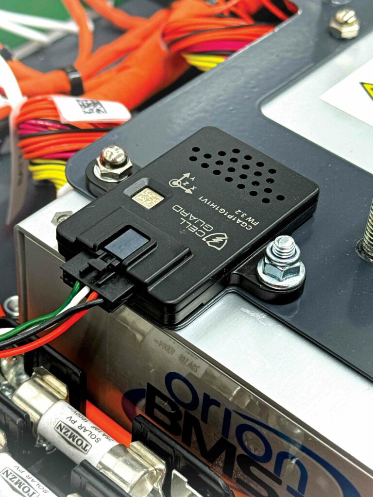
For detailed battery health monitoring, the XP-1’s BMS integrates Metis Engineering’s Cell Guard multi-sensor device, which internally monitors at the module and pack levels for humidity, gases with volatile organic compounds, absolute pressure and temperature as standard.
“It senses moisture on a parts-per-million basis, thereby tracking not just the presence but build-ups of moisture, including setting a maximum level above which it is safe to assume water is leaking into the pack and risking a short across what used to be air gaps between the cell groups,” Hazell adds.
“People tend to take our retrofitted vehicles into pretty poor weather, often wading into flooded roads with them, or even jet-washing them, all while assuming it is going to be waterproof forever. So, if we detect too much moisture, or a certain limit value for gases or venting from cells, the BMS can open the contactors to keep it from turning into a thermal event.”
The Metis Cell Guard has a G-sensor for impact and crash detection, enabling Fellten to set a target number specific to the crash levels of G-force for each EV and pack. Upon sensing anything at or above that value, the Cell Guard triggers the BMS to open its contactors and stop the battery pack operating.
Charge management
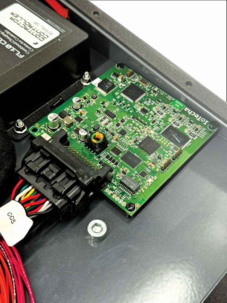
Considerable effort has been made to install safe and precise control of the CCS rapid charging system into the battery pack. Principle governance of charging, and the associated communications between vehicle and grid are handled by a control module from US-based IoTecha.
“Handling comms between the charger and grid is quite an in-depth process, not least because you’re going from CAN bus through a Linux software system into the powerline communication bus, and then back,” Hazell says.
“Back in the days of CHAdeMO, it was all just CAN bus comms, which kept things easy. But now that effective charging takes conversion between one comms protocol to another, it’s become a much more technical field, and the required software stack has become larger and more complex. So, we source a solution from IoTecha, which handles that portion of the process, but separately, our contactor control system has to do all the other work to enable IoTecha’s module to function.”
That other work includes extracting charging-critical data from the BMS, and translating it into maximum, minimum and other requirements on power, voltage and current, which form clear and simple instructions for the charger to follow (fast-charger systems being comparatively simple devices, the burden is often entirely on the vehicle to select and request the correct delivery rate of electricity).
“There’s further complications in that the EV needs to vary its metrics and instructions sent to the charger, based on the information it draws from the charger,” Hazell says.
“For instance, we found out recently that if a charger ‘tells’ you it can only output a maximum of, say, 100 A, you need to ask for 100 A specifically, because if you ask for more, the charger might react by shutting down since it can’t fulfil what you’re requesting. There are many similar issues that we’ve had to handle, so the battery outputs the relevant signals, based on the feedback from the IoTecha unit.”

The contactor controller in Fellten’s pack also controls LEDs for starting, continuing and stopping a recharge session, and a lock pin that prevents the driver from pulling out the charge port during charging and the ensuing arcing hazard across the pins. Another LED is present for flashing code sequences to customers approaching the EV charge port; these sequences correspond to specific faults detected by the system, encompassing HV faults, lock motor faults and others explained in the EV owner’s handbook provided by Fellten.
Fellten has developed its own system for pre-charging the HV bus. It was created to resolve issues with pre-charge scenarios, particularly when sensing whether vehicles had been pre-charged correctly, as standard timing- or inverter-based sensing approaches could sometimes cause pre-charge relays to burn out after time, or result in incorrect pre-charging or overheating of resistors during power-up.
“Our system monitors the temperature of the pre-charge devices to ensure they don’t overheat and also performs live HV sensing. Our contactor controller board has HV sensors on it, tuned for accuracy to within 400 mV,” Hazell says.
“As an EV comes alive, the system can make certain all the capacitors in the inverter and charger are full before we close the main contactors, so we don’t get a sudden spike from 0 to 400 V and blow out a set of components. Our system can sense within milliseconds if pre-charge conditions aren’t optimal – whether on one side of the bus or the other – and within a second it will shut off the main positive terminal to stop the pre-charge, so the rest of the surrounding subsystems can be brought up to the required standard voltage.
“It won’t close the contactors until the bus is within 5 V of the source voltage. If the EV bus won’t get up to that voltage, then it normally means you’ve got a dead short, a grounding issue or something else wrong in the system. So, by doing it this way, we’re saving components in a lot of instances, because we then don’t risk blowing a fuse or melting a cable by shutting the contactors and allowing a dead short to happen.”
Interconnections
To date, Fellten has usually opted to buy overstocked (but still new and unused) modules from OEMs, resulting in the use of the VDA 355 module in the XP-1 packs. These are made by DFD Energy with NMC cells of either a pouch or prismatic design, depending on request.
Those in the XP-1 each feature 12 pouch cells (with two parallel-connected strings of six series-connected cells) and housed in aluminium. More energy-dense options were available, but the 6S arrangement was paramount to Fellten’s voltage requirements for compatibility with the inverter.
“We’d like to push to LFP or LMFP, but the energy density we want isn’t available with those chemistries just yet, though when we start manufacturing our own modules, we’ll be able to pick and choose from various cell options,” Hazell says.
“That’s a big motivator for us: conversion specialists like us can only get modules that have been commissioned to be built in volume by large OEMs, so we’re limited to use what the OEMs want to use. Our Porsche systems, for instance, use an overstocked module from XPENG, and our Universal Battery Packs use the Volkswagen modules built for the ID.3 and ID.4, which use LG cells.”
Overall, the XP-1’s pack contains 14 modules arranged in a 2P84S configuration, resulting in a 320 V nominal bus voltage. The nickel-plated, copper busbars connecting the modules are treated with a special powder coating for HV insulation, giving what Hazell describes as a thick, orange coat that is extremely resistant to removal attempts and stays robust against any accidental impact during assembly.
Acetone or a similar chemical is applied onto the faces of the module connections to protect against any contaminants that could cause high resistance points to form on the busbars. “Even oils from your fingers can cause high resistance points to form, so the interconnections must be made as cleanly as possible,” Hazell notes.
Nord-Lock washers are typically used when bolting the busbars onto the modules. While more costly than other washers, including the far more commonly chosen Loctite washer, Fellten has found the latter to be lacking in thermal performance.
“You heat Loctite washers to break them away; that’s the primary issue with how they’re designed. If you do repeated charge-discharge cycles in close contact with them, in which you’re frequently hitting 60-70 C temperatures, with your busbars heating up and cooling down, then there’s a decent probability of your Loctites getting to the point where they soften or give way,” Hazell says.
“Nord-Lock washers consist of a two-part, serrated, interlocking design. As you tighten them, they twist and lock together to create a self-maintaining, continuous force. They’re about £1 per washer, so not cheap, but they basically never come loose and the pressure isn’t on the thread. That means if you ever have to replace a module in the XP-1, there isn’t a risk of ripping the thread or damaging it inside the module itself.
“Contrast that with instances we’ve seen in some packs where the customer, or their technicians, couldn’t apply heat to remove their Loctite washers, because it would have risked damaging the modules, and that made maintenance and repair really difficult. There are other alternatives, like liquid PTFE thread seals, but, for us, the Nord-Lock is easier to work with because there is no chance of variation or inconsistency with how much liquid sealant gets applied, or how much gets in between the busbar layers as you’re putting it in. It’s a solid washer that gets torqued to a set figure.”
Manufacturing plans
As of writing, Fellten is constructing a new, 15,000 ft2 facility, adjacent to its main building, to expand its pack manufacturing. Another unit adjacent to the new facility is being refitted as a stock holding and control warehouse.
Next to that will be its aforementioned module-manufacturing centre, the design for which is now complete and intended not just for resto-modding applications, but also for batch production of high-end packs for
low-volume EV manufacturers.
“The module facility will be a temperature-controlled, insulated unit, stocked with production machinery revolving around prismatic cells,” says Hazell. “That will enable us to make equivalent solutions to VDA 355 and 590 modules using the same machines, outputting a mix of the two at will, instead of minimum runs of one or the other.”
First in this production line will be the sorting machinery, which puts incoming cells into eight different channels (plus a ‘no good’ channel), depending on what each cell exhibits during resistance testing prior to sorting. This ensures cells of similar resistance are grouped together in modules for consistent charge and discharge pressure.
“That’s especially important if you’re stringing cells together in parallel. You don’t want one cell with a slightly different resistance to the others around it, because it will charge and discharge at a different speed, leading to degradation in the cell group and then huge knock-on effects in its later life,” Hazell says.
After being sorted, the cells will run through a machine that laser-cleans each of their terminals of contaminants and scans their barcodes for traceability. Then, the cells will be stacked into a compression rig, where the module casing is put on and pressed to a set torque value (like pouch cells, prismatic cells must be compressed to a minimum amount of pressure) with either a non-conductive glue or sheet lining between and around the cells to prevent metal-to-metal contact.
Some laser welding of the edges may occur to maintain compression of the modules, after which they will move into a station for installing the busbars in series or parallel, as needed, with a laser-welding system to bond them simultaneously as another rig applies pressure to hold them in place.
“We will also be running imaging analysis all the way through to make sure each weld shows the right penetration, no contaminants, just consistency all around. Each module will then be delivered with a photograph of every single weld – all that and additional data being accessible via its barcode,” Hazell says.
“Then the BMS gets installed. A lot of OEMs will use ribbon cables or small wires to link all the cells, temp sensors and so on. But, as mentioned, we’ll use a slave BMS board instead, with just a four-pin connector to do all the cell balancing within the module, and that will be standardised across all our modules, whether 6S, 4S or something else.”
Fellten produces all of its own wiring harnesses in-house via automated crimping machines, TUV-approved training programmes (as wire harnesses still largely need human hands to be weaved) and the Arcadia software from Cadonix, which many OEMs use for designing and testing.
“On top of that, the overall approach to this facility means we’ll get to standardise our cell stock, our busbars, our cable stock, our software. People say it’s not cost-effective to build modules in the UK, but we see a huge cost-saving opportunity via just-in-time [JIT] manufacturing, as we won’t need to hold masses of stock,” Hazell adds.
“We will build modules as and when we need to, and then the modules in the packs will be fresher – they won’t have sat rocking on a container ship for six weeks, so they will be of a better quality.”
Early-stage CAD of new Fellten modules will include simulations of up to 20 G crashes for safety rating the designs. Once built, each new pack will go through comprehensive charge/discharge cycling, as machinery for rapid charging and discharging is already present at the company’s plant, and include one 100 kW rig and another 400 kW system.
“We can cycle each module and pack contextually, based on BMS data, meaning we can limit based on the DC out or constant current out, or tailor the peaks and troughs of the cycle to match, for instance, someone taking a pack meant for a Porsche 911 and pushing it really hard on a track,” Hazell says. “That will also help us get our BMS profile dead on, to limit the batteries at the right time and smoothly, so drivers never feel a hard limit coming in.”
Some of these cycles will be performed with the pack lid removed and a thermal camera pointed at the modules to detect hotspots in the busbars or elsewhere. As some shorter busbars may feature flexible joints – composed of multiple, thin, ultrasonically-welded layers – to compensate for the lower resistances, it will be critical to check there are no contaminants or damage that risk causing performance losses later in the pack’s life.
As Fellten looks towards R100 certification, it will begin crash- or crush-testing modules, as well as shake tests, fire tests, dead short tests, and over-charge and over-discharge tests.
Pack assembly
Today, the pack enclosure is made from steel, with Fellten having avoided the more lightweight aluminium for several reasons. For one, the company has found that building packs from aluminium eventually mandates using very thick sheets of it to achieve the ideal structural strength.
“Additionally, from a crash-safety perspective, steel is a better choice,” Hazell adds. “Most OEMs don’t need to worry too much about what the pack is made from as they will just sling their packs under the vehicle floor, and then when the crash inevitably comes from the front, rear or side, there is low to zero risk of a pack deforming or flying into a driver or passenger. But, with retrofitted EVs, the battery pack is more likely in the front or rear, so you need to build an extra degree of crash resistance into the pack, so that if the pack takes a knock, it withstands the impact and doesn’t deform or move too much.”
Fellten has simulated virtual crash tests of up to 20 G to visualise how the pack and its mounts distort against hard shocks, and to determine the best material and design approaches to minimise the chance of a thermal event or other hazardous consequences. Some customers of the 55 kWh pack have chosen to perform full crash scenarios to validate that it will remain in one piece without any significant deformation (even if the test car itself is destroyed).
Furthermore, aluminium comes with a significantly lower melting point than steel. While Fellten has never had a fire break out in or around one of its packs, and judges that such instances are far rarer in the EV world than social media lets on, it also judges steel as providing a desirable minimum level of fire tolerance and hence safety.
“We always think with the worst-case scenario in mind, and that has dictated a lot of what we’ve done on the enclosure end. With the XP-1 pack and several others we’ve made, we go with a
3 mm-thick steel base, with 1.5 mm steel for the upper section, and those are joined by sheets around the middle of the pack,” Hazell says.
“That allows us to build the modules into the enclosure base easily and then put the lid section on, and as that goes together, the cooling plates all tie throughout the battery pack and bolt to the housing walls to make it rigid. As we’ve taken this approach to the cooling plates that allows for modular pack assembly, we can also connect a section of plates, modules and busbars together, which then gets lifted and lowered into the pack; then build the next section and lower it alongside the first one, installing them part by part, with the connection of each series coming afterwards.”
Regardless of the approach taken with modular construction, the pack is designed with a split down the middle, such that the positive and negative are never connected (an approach similarly taken by Xerotech, as seen in EME 22, November/December 2022) until the final stages of assembly, during which the safety disconnect devices are installed last.
“That saves our team or end-users’ technicians from having to work with huge quantities of safety gear on. Trying to work nuts and bolts with massive, HV-protective gloves on is extremely difficult, and the risk of someone dropping tiny, metal components into a battery pack is actually really high,” Hazell notes.
“In both the XP-1’s pack and our 55 kWh pack, the HV plate is at the very top section of the modules, so it can be pre-assembled before the lid goes on. That plate constitutes the BMS, contactor controller and the
pre-charge system. As the lid lowers on, there are two bolting locations in the HV plate, corresponding to the positive and negative terminals that run up into the lid from the lower part of the pack, so the moment where the lid goes on is the only point in the entire assembly process where HV gloves are needed. After that, the pack can be delivered to the installer or taken for testing.”
Future
Fellten’s principle aim with Morgan, as with many customers, has been to enable a non-EV company to move into the EV space, without that company needing to dilute its focus away from its own specialisations with new skill requirements, such as battery manufacturing, BMS design or charge protocol programming.
“The XP-1 may be a prototype, but Morgan now knows it can make the transition into EVs quite easily, should it decide to. It’s a similar experience to that we had before, with BMW and their Classic Mini,” Hazell recounts.
“There was no way BMW was going to develop a Classic Mini retrofit solution. It was never going to be cost-effective. But, with us, we’ve been able to produce the Mini system, supply it all to Recharge Heritage with the BMW branding on it, and bring it to market with the BMW wings.
“There are other companies we’re working with, and a similar thread runs through them all in that they are long-established companies, which produce vehicles but need to start thinking about EVs, and they’re missing either the time, the resources or the staffing to just switch from combustion to electric powertrains. It’s a different world, but we can take care of the electrical, technical aspects for them, and they get to focus on building beautiful vehicles.”
Indeed, the XP-1 has received positive reviews, and is now in testing until mid-to-late 2025, with the ball in Morgan’s court as to whether it will focus on producing this electric design or another in series.
In the meantime, Fellten is ramping up its capacity for module and pack manufacturing, touting significant room for further cost-optimisation across its present and planned facilities, and it plans to target overseas markets in the US and elsewhere. These will not just be limited to conversion systems, however, as Fellten’s customer base also includes energy banks for a solar-powered car-recharging park, being made by 3ti.
“The 3ti system will be a containerised, IP-rated, interlinkable pack system that can be dropped into a car park wherever EVs need to be driven, parked and charged at short notice,” Hazell says.
“Simultaneously, we’re working on a product called the Charge Qube, which is a 100 kWh Euro-pallet-sized battery pack with CCS rapid charging in and out. One day, that could be taken to race tracks along with the Caterham to do two full recharges of the car on track.
“Our next big in-house project is going to be a 50 kWh pack for Caterham, which will show how we can build something for the higher-performance sports-car world rather than the
classic-car world.”
Key suppliers
Battery modules: DFD Energy
Cells: DFD Energy
BMS hardware: Orion
BMS software: Brill Power
Cell-monitoring sensor module: Metis Engineering
Charging control module: IoTecha
Wiring harness design software: Cadonix
Washers: Nord-Lock
Inverter: iNetic
ONLINE PARTNERS


