Combined approach to HV tests

Vector and CSM have combined their measurement technologies to validate e-mobility platforms up to 800 V (writes Nick Flaherty).
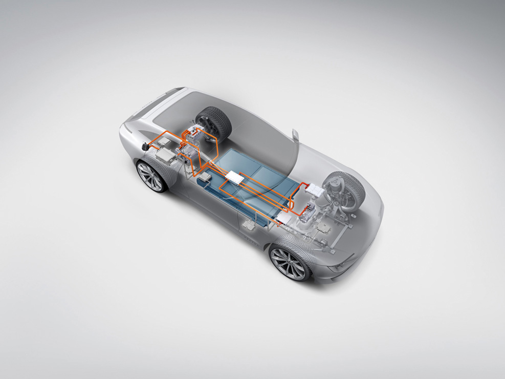
The layouts of the powertrain, the charging components and the HV elements present new requirements for test and validation, which vary from vehicle to vehicle depending on the electrical system topology and the voltage levels in the low and high-voltage systems. There are also varying requirements for load and dynamic response.
That makes validating the electric motor, battery, inverter, onboard charger, electric heater, electric compressor and DC-DC converter a real challenge. Combining HV-safe measurement modules, ECU measurement technology and software for synchronised online acquisition of measurement data and data analysis during the road tests can provide key validation data.
The validation involves very high requirements for sampling rate, HV safety and scalability of the measurement system used. The entire HV electrical system has to be instrumented and sampled at numerous points to ensure that all the HV system’s components perform their tasks and operate in every conceivable driving situation.
The measurements must be made at very high sampling rates to acquire and quantify additional effects such as voltage peaks caused by line inductances, abrupt load alternation or capacitive coupling of fast switching processes in the power electronics. To analyse the causes of errors, all these measurements must be time-synchronous and must not originate from different measurement systems that are not coupled.

Besides transmitting measurement parameters on the various vehicle buses, the ECUs in the vehicle also provide information that is relevant and important for validation. That is why the information is measured time-synchronously and needs to be incorporated into the evaluation of overall behaviour.
Validation conducted under extreme driving and operating conditions ensures that the specific design of the HV electrical system in the vehicle has sufficient voltage margin without imposing any limitations on vehicle operation. The road tests conducted for this purpose can also examine the effects of two electric motors with superimposed interferences.
Since voltage peaks are very fast and sporadic, and the tester needs this precise information during the drive, the measurement software must be able to evaluate the signals online, to calculate triggers for starting recording for example. The trigger condition might be derived from the voltage signal over time, say, to detect whether a maximum value is exceeded during fast changes in voltage.
The HV breakout modules(HV BMs) from CSM are designed for decentralised and safe measurement applications on high-voltage cables. Various HV BM shunt modules are available for the HV network; they are permanently installed and are available over a nominal current range of 50 to 800 A.
Current and voltage are acquired synchronously in the HV BMs at a data rate of up to 1 MHz (1 μs). The precision of current and voltage measurement is better than 0.2%.
The Vector network interfaces enable users to acquire information on ECUs over all available bus technologies and protocols.
ONLINE PARTNERS


