

")


")


Coil windings
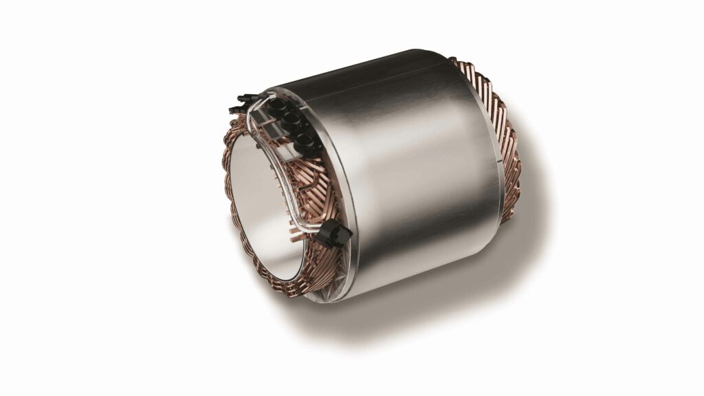
(Image courtesy of ZF)
In the loop
Peter Donaldson takes electric machines apart to examine the inner workings of coil windings
At first glance, electric machines are simple. They have one moving part, the rotor, which either rotates in response to an input of electrical energy or puts out an electric current in response to an input of mechanical energy that rotates it.
Inside the machine, things get more complicated as its basic functions – besides crucial parameters, such as torque, power, speed, energy efficiency and controllability – depend on the interaction of magnetic fields that push and pull each other.
Some electrical machines create all their magnetic fields by passing electric currents though coils of wire wound onto cores, while others use a combination of permanent magnets and coil windings.
These windings may be in the machine’s rotor or stator, or both. In all cases, they are essential components whose design has a profound effect on the behaviour of the machine and its suitability for the intended application.
Windings affect performance through numerous interacting factors, including switching sequences and frequencies, resistance, reluctance, voltage and current constants, heat dissipation and mechanical strength. They can also be made of different conductive materials and in various multiple configurations, with pros and cons for each application, bringing complexity to the choices that engineers must make.
(Image courtesy of Zeiss)
Coil anatomy
When an electric current flows through the windings (which form a closed loop) it generates a magnetic field made up of lines of force in accordance with Ampere’s law. Consisting of wire looped around an iron core, the induction coil functions as an electromagnet and, like a permanent magnet, it has north and south poles.
The core provides a path for the magnetic field to move through, and the conductor typically fits into slots in the core, which is usually laminated with insulating material between thin layers of iron to minimise heat-generating eddy-current losses. Magnetic forces act in a direction that tends to shorten the field lines between opposing poles, attracting north and south to each other.
Torque at the rotor of an electric machine is related to the force acting on a current-carrying conductor in a magnetic field (Lorentz force) and it changes in reluctance, which is to magnetic fields what resistance is to electric currents. Both allow the conversion of electrical energy into mechanical energy and vice versa.
In alternating current (AC) machines, for example, such as induction motors (IM) and synchronous motors (SM), the windings are arranged in specific patterns, and switched on and off in sequence to create a rotating magnetic field that causes the rotor to spin.
The windings are typically arranged in phases, which are electric circuits isolated from one another, so they can be switched on and off separately. In a three-phase AC induction motor, for example, the phases are arranged 120o apart to ensure smooth power delivery.
By changing the amplitude, frequency and phase of the current flowing through the windings, the motor’s speed, torque and direction of rotation can be controlled. Also, by optimising factors such as the number of turns, wire gauge and winding pattern, engineers can improve the motor’s efficiency, reducing energy losses and boosting overall performance.
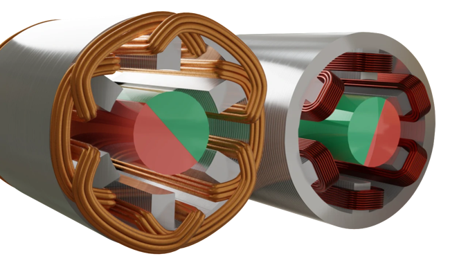
(Image courtesy of Oswos)
In pursuit of efficiency
Therefore, to meet demand for greater energy efficiency, and higher torque and power density from electrical machines, engineers pay close attention to the windings. They often focus on reducing ohmic losses (electrical resistance), says Markus Anders from Siemens Digital Industries Software, a manufacturer of simulation-based, e-machine design tools.
“This can be done either by using a better conductive material than copper, by keeping the temperature of the wires as low as possible, or by simply getting more of the conductive material into the slot, thereby increasing the so-called slot fill factor,” he says.
Slot fill refers to the percentage of the slot area occupied by the stator windings. As well as reducing ohmic losses, increasing slot fill can enhance the electromagnetic performance of the motor by increasing the ampere-turns and improving the torque density.
“Resistance increases as the temperature goes up,” Anders says. “Generally, this will mean we need to have sufficient direct cooling of the wires/coil sides/windings. Another measure that supports the loss reduction is to get the mean length per turn within a coil as short as possible, again helping to reduce the coil resistance or overall phase resistance.”
Juho Montonen of Danfoss Editron agrees higher slot fill is a key factor in improving energy efficiency, along with the exploitation of a higher space factor.
As a concept, the space factor is related to slot fill, but it is not identical as it refers to the ratio of the cross-sectional area of copper conductors to the total slot area, including both the copper/conductor and the insulation.
It provides a measure of the efficiency with which the available slot space is used for carrying current. Increasing the space factor includes optimising the design to minimise the amount of insulation and maximise the amount of copper/conductor.
Increasing torque density usually necessitates more effective cooling to the windings, which is another reason to adopt direct cooling, Montonen says. The catch is that higher power and torque density do not always mean higher efficiency. “The smaller the motor gets, the bigger the share of losses where effective cooling takes place.”
(Image courtesy of Amada Weld Tech)
Winding taxonomy
Given their importance, it is not surprising there are many types of windings in use in motors and generators developed for e-mobility applications, and that they are the focus of considerable r&d attention. Certain types of winding are commonly associated with specific types of e-machine, although the choice of winding configuration depends on factors such as motor design, the intended application, control strategy and performance requirements, so the associations are not set in stone.
For example, concentrated windings, also known as single-layer windings, involve winding all the turns of a phase in a single layer, concentrated in one or a few slots. This shortens the mean length per turn of the conductor material, and with that the phase or winding resistance is kept as low as possible, Anders says. At the same time, the reduction in axial space occupied by the end-turns allows for additional active material, producing higher torque in a given volume, he adds.
Concentrated windings are commonly associated with permanent magnet synchronous motors (PMSMs) and sometimes with brushless DC (BLDC) motors. They are relatively simple to construct and control, making them well suited to applications requiring precise torque control, high efficiency and compact design.
As the name suggests, in distributed windings the turns of a phase are spread across multiple slots on the stator. Commonly found in IMs, synchronous reluctance motors (SynRMs) and some types of switched reluctance motors (SRMs), distributed windings help to reduce harmonics, improve torque production and minimise torque ripple, making them suitable for applications where smooth and efficient operation is prioritised.
In lap windings, the end of one coil is connected to the start of the next in a continuous manner. Often used in DC motors, universal motors (which can operate on either AC or DC power) and in some types of AC motor, lap windings allow for more poles. In DC motors they enable better speed control and torque characteristics.
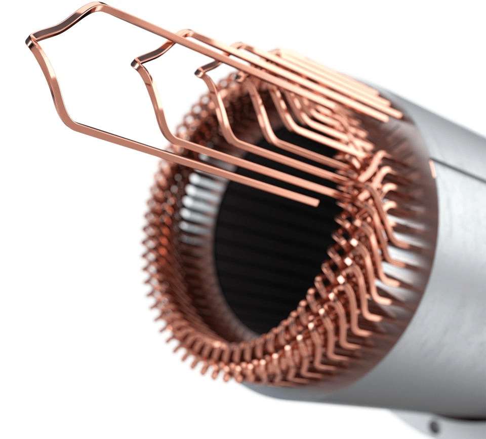
Wave winding is a configuration in which each coil side progresses through a number of slots and then returns to the starting point. The end of one coil is connected to the start of another with either the same polarity or a different one, depending on the application. In the latter case, this allows for higher voltage ratings and improved cooling due to better air circulation between the coils. Wave windings are commonly used in high-speed AC motors and generators.
With fractional slot winding there is a non-integer number of slots per pole per phase, with numbers such as 3/2, 5/4, 7/6, 9/8 and 11/10 being fairly common. Often found in interior permanent magnet (IPM) motors and some PMSMs, fractional slot windings offer lower torque ripple, higher power density and enhanced flux weakening. The latter reduces the back electromotive force (back EMF) as rpm rises to extend the speed range of a PMSM.
Random windings feature coils placed randomly in the stator slots. Also known as distributed random windings or stochastic windings. In EVs, they are typically used in special applications where specific performance characteristics are required. Their irregular and distributed coil arrangement helps to reduce electromagnetic vibrations and noise from the motor, enhancing passenger comfort. They can also be easier to cool than other types, thanks to better air circulation and heat dissipation within the motor.
Further, irregular coil distribution can help to minimise losses associated with coil proximity and slot effects, resulting in more uniform magnetic-flux distribution and reduced winding losses, in turn leading to increased efficiency.
Finally, random windings tend to produce lower harmonic distortion than other winding types. Reducing harmonic content in the magnetic field results in smoother motor operation and reduced electromagnetic interference, further improving efficiency and reliability.
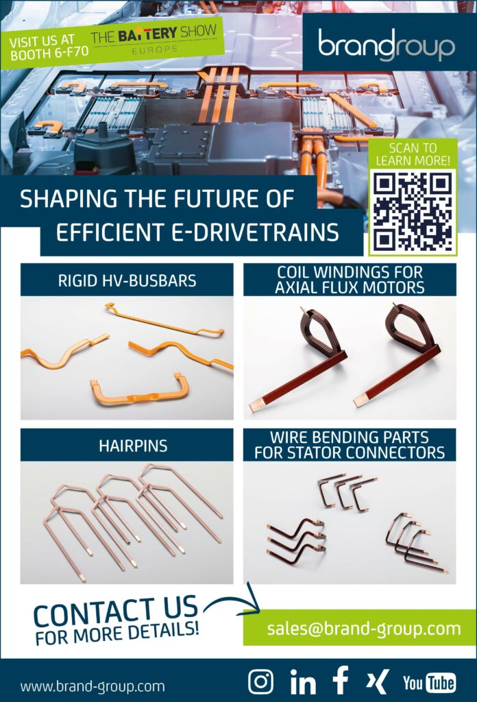
Hairpin windings use pre-formed conductor bars that are shaped like hairpins and inserted into the slots of the stator core. Advantages include reduced end-winding losses, higher slot fill, improved thermal performance and increased power density. Hairpin windings are increasingly used in PMSMs for EV propulsion, more of which later.
“You will find the more traditional distributed windings along with the concentrated windings are prevalent, as well as the hairpin type, with the most recent trends more towards the hairpin technology,” says Anders.
(Image courtesy of Zeiss)
Pros and cons
Given the large number of options and extra complexity arising from the possibility of combining different windings, our experts have given guidance on some of the important pros and cons of various types.
With concentrated windings and the fractional slot type, the key advantages are the shorter end-turns that lead to lower resistance and better utilisation of the available volume, along with less need for insulation because the end-turns do not cross, says Anders.
On the minus side, sub- and higher harmonics of the air-gap flux density cause additional – and significant – eddy current losses, he notes.
Further, concentrated windings may be more susceptible to coil instability or movement during operation.
Distributed, random, lap and single-layer windings have less harmonic content in the air-gap flux density, and because there is only one coil side per slot and less insulation, there is more space left for conductor material, Anders explains. Cons include longer end-turns and consequent higher resistance, and the need for more axial space to accommodate them.
With double-layer windings, however, short-pitched schemes can help suppress unwanted harmonics, but the requirement for insulation is greater due to the presence of two coil sides of different phases in one slot.
The main benefits of hairpin and wave configurations are the greater fill factor, and the consequent lower overall phase resistance they allow, somewhat offset by higher manufacturing costs, he says.
Montonen concurs that the short-end winding types, despite their lower resistance, represent poor solutions for high-speed machines. Meanwhile, distributed windings benefit from mature manufacturing know-how, and single-layer windings lend themselves easily to automated manufacture, but they have longer end-windings that increase resistance.
In terms of application, hairpin windings are now the most commonly used type in high-performance electric cars, Montonen says. They can also be found in large roadgoing EVs, such as trucks and buses, as can random distributed windings. In light EVs, where economy and energy efficiency have a higher priority than performance, hairpins and aluminium windings are also common choices.
A major reason for the broad application of hairpin windings is their excellent thermal performance in comparison with other types. They are solid conductors in contrast with the stranded wire types and can therefore achieve a high fill factor, making them very attractive where high power density and efficiency are needed.
They also lend themselves to highly automated manufacturing processes using advanced winding machines with different processes, whereby the hairpins are inserted either axially or radially into the slots. Typically, the conductor is bent into a U-shape and inserted into the stator slots, and the end is then twisted and welded to the neighbouring hairpin.
There is an alternative process whereby the conductor is bent to shape the entire winding, allowing these pre-shaped conductors to be inserted into the stator slots without the need to weld them to their neighbours, according to Xue et al in their 2021 paper, ‘Optimisation of Hairpin Winding in Electric Traction Motor Applications’.
A further advance in manufacturing has come with the introduction of technology that allows the use of square wires, providing a high slot fill, and lowering the resistance and consequent ohmic losses once more. Also, these thicker conductors may be made of hollow wires, allowing for direct liquid cooling, Anders points out.
“However, this requires care as the larger conductor sizes open the door for induced eddy currents and proximity effects, which increase resistance, especially at higher speeds. The manufacturer must pay attention,” he cautions.
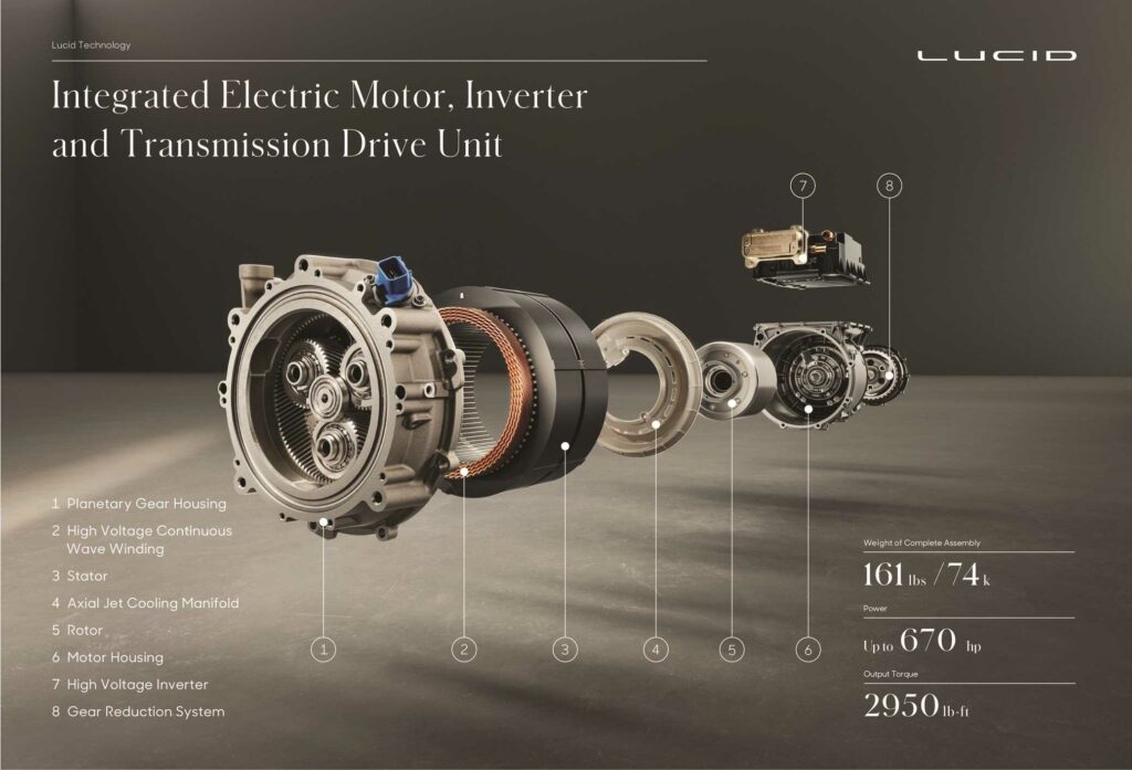
(Image courtesy of Lucid)
Litz wire, skin and proximity
When the highest power densities are required for electric aircraft applications, the conductors often take the form of Litz wire, Montonen points out. Litz wire consists of multiple, individually insulated strands that are woven together. By distributing the current across many strands, Litz wire helps to mitigate the skin and proximity effects, and the consequent resistance and power losses at the high switching frequencies common in high-performance motors.
AC tends to flow more towards the outer surface of a conductor rather than being evenly distributed throughout its cross-section. This is the skin effect, and it increases with switching frequency. Similarly, the proximity effect tends to concentrate current flow through a conductor towards the surfaces facing neighbouring conductors. Both phenomena reduce the effective cross-section of the conductor, increasing resistance.
As well as reducing these undesirable effects, Litz wire’s multi-strand construction allows it to maintain flexibility while carrying high currents, which can be crucial in applications where space is limited. This construction also permits better heat dissipation, compared with monolithic conductors.
Together, these characteristics enable Litz wire to carry high currents more efficiently in a cross-sectional area, contributing to higher power densities, reduced weight and, consequently, a greater payload in aircraft.
Integrating this kind of wire into e-machines brings design and assembly challenges. For example, ensuring proper termination and insulation of each individual strand within the motor’s winding can be difficult and may require custom solutions.
Further, Litz wire’s construction from individually insulated strands may need extra space in the form of larger slots or more winding layers.
To take advantage of Litz wire’s good heat dissipation characteristics demands careful thermal design and may also require improved ventilation or cooling channels in the motor structure.
Originally developed to carry AC in communication and radar applications, Litz wire designs tend to be optimised for specific AC frequencies. Designing conductors to perform well over the wide range of frequencies encountered in variable-speed propulsion motors can be complex, and it may require sophisticated modelling and simulation tools.
Also, weaving together multiple, individually insulated strands to make Litz wire is an intricate process that can be labour-intensive or require specialised machinery, leading to higher production costs, although there have been recent advances in this area.
One of these is formed Litz wire winding (FLW), consisting of bars made by compressing twisted bundles of parallel, connected strands and compacting them to achieve a high slot fill factor.
According to Dimier et al in their 2020 paper, Comparison of Stator Winding Technologies for High-Speed Motors in Electric Propulsion Systems, the individually insulated strands are continuously transposed along the axial direction of the motor in predefined positions. Skin and proximity effects are minimised by the use of strands with small cross-sections.
“The axial transposition ensures a balanced thermal behaviour of the FLW bar. A thin-strand insulation is sufficient since the voltage difference between parallel strands is small. The insulation to the stator or other phases is realised for the whole bar,” the researchers say.
One FLW manufacturer in the automotive sector, Hofer Powertrain, claims that losses in the motor are reduced by 25% and that hairpin-winding production lines can be adapted to FLW easily.
Conductor and core
Material selection is also a key winding-related decision that affects performance in terms of electrical and thermal conductivity, and cost, Montonen notes. The mainstream options for e-mobility applications are copper, aluminium and alloys that mix copper with aluminium or silicon.
As Anders explains, aluminium has a lower conductivity than copper, and therefore more space needs to be provided for the wires. If the winding losses must be identical to those of copper windings, this leads to slots with bigger cross-sections and an increase in total machine volume. Otherwise, efficiency will decrease with slot cross-sections that remain the same, which might be acceptable if cost is prioritised.
Another important point from a manufacturing point of view is that the tensile strength of copper is significantly higher than that of aluminium. This may cause problems with aluminium during the manufacturing process, and possibly make the conductor more susceptible to fatigue and limit the overall lifetime of the machine, he cautions.
The choice of winding material can also have an impact on the choice of core/lamination material, which must have compatible magnetic properties to ensure efficient energy conversion and minimise losses. For example, copper windings have electrical conductivity and lower resistivity, so a core material with high magnetic permeability, such as silicon steel, is typically chosen to maximise magnetic-flux density and minimise core losses.
Anders notes that as aluminium wires require more space than copper ones, it might be an option to use a lamination material that allows for higher flux densities to compensate, but then the price advantage might be in question as better lamination materials come at a price premium.
Montonen points out that the conductivity of the winding material dictates the shape of the slots in the core, while the saturation levels of the selected lamination materials affect the thickness of stator teeth. “It is the combination of these two and an iterative design process that enable the maximum amount of winding material to be fitted into the slot,” he adds.
Winding and core materials should also have similar coefficients of thermal expansion to minimise the risk of excessive mechanical stresses from thermal cycling in operation, which can cause fatigue damage over time.
The higher resistivity of windings made from aluminium or its alloys may generate more heat than copper windings, so core materials with higher thermal conductivity, perhaps combined with improved thermal management features such as active cooling may be needed.
There are more exotic options in winding materials for specialised tasks. Silver, for example, offers the highest electrical conductivity among common metals, making it well suited to high-performance applications where minimising electrical losses is critical. If that need is extreme, superconducting materials such as niobium-titanium alloys, for example, exhibit zero resistance at cryogenic temperatures at the cost of a very complex and costly cooling system.
Other specialised requirements, such as improved thermal stability or resistance to vibration and mechanical stress, can be met by composite conductors made from reinforced resins that incorporate conductive particles such as carbon nanotubes.
Future directions
Danfoss, which specialises in distributed and concentrated non-overlapping windings, has incorporated lessons from prototype-level studies of different windings optimised with cooling for high torque density use, Montonen says. Looking to the foreseeable future, he considers that Litz wire could be a revolutionary challenger to solid, copper hairpins, even though it has mainly been used in research projects and aerospace applications so far.
Finally, he anticipates future use of oxidised copper, which has an oxide layer on the surface of the conductor. This has a number of benefits, including the prevention of further oxidation (corrosion) in general, but particularly at high temperatures, enhancing its thermal stability and extending its service life, while also mitigating the skin effect. Further, oxidised copper windings can be produced using environmentally-friendly processes that minimise the use of hazardous chemicals and reduce waste.
ONLINE PARTNERS


