


")


")


Battery tech for heavy duty applications
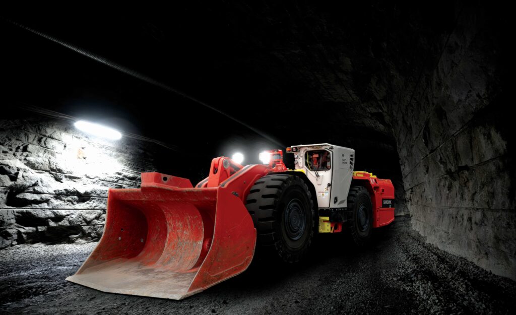
(Image courtesy of Sandvik)
Heavy metal
With applications ranging from trucks to mining equipment and excavators, vehicle assemblers have a wide pool of requirements, as Nick Flaherty reports
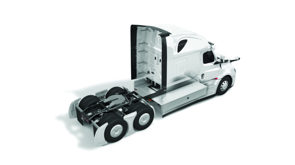
Flexibility is a key requirement for heavy-duty electric vehicle (EV) applications. These vehicles are based on existing chassis designed for diesel engines, so battery packs with various chemistries have to be manufactured to fit a wide range of form factors. With all the different battery cell formats for different chemistries, from cylindrical to prismatic, and varying safety requirements, there are many design tradeoffs.
These designs cover commercial trucks from light Class 3 to heavy Class 8, as well as buses, and they need a standard connector for the charging system. The Megawatt Charging System (MCS) is being rolled out to enable them to charge in a wider range of places, rather than being limited to the depot because they use a proprietary system connector.
Heavy-duty applications also include mining and drilling machines, which have varying ways of providing power, from long cables and overhead power gantries to swappable battery packs.
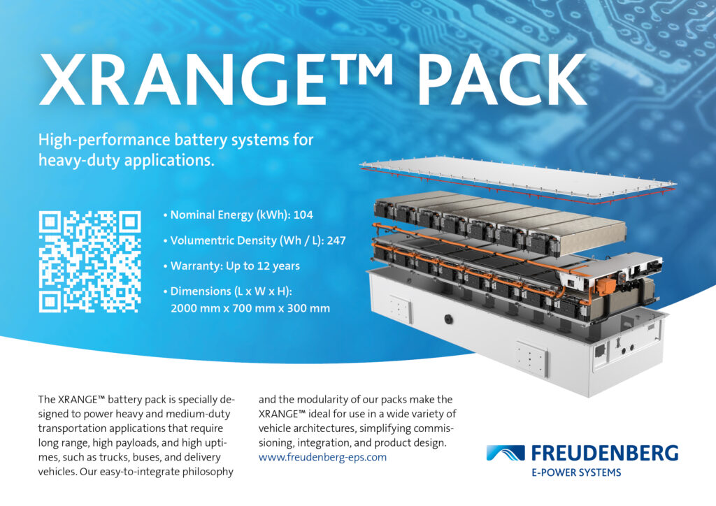
(Image courtesy of Freudenberg E-Power Systems)
Battery chemistries
Lithium-ion cells with nickel, manganese and cobalt (NMC) currently have the highest energy commercially available, with capacity of 150-270 Wh/kg.
Lithium iron phosphate (LFP) cylindrical cells have a lower energy density, of 90-160 Wh/kg at cell level, but their inherent safety, avoiding thermal runaway, however, a LFP pack will be heavier than a comparable NMC pack. This increases overall energy density, especially as there are hundreds of cells in a heavy-duty application.
Lithium titanate oxide (LTO) cells are also used for heavy-duty applications, particularly as they operate at low temperatures down to -30 C without the safety concerns of lithium-ion cells. They have a lower typical power density of 50-80 Wh/kg but the supply of the prismatic cells is more limited.
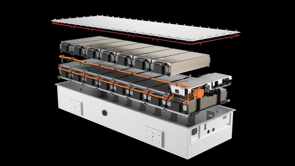
(Image courtesy of American Battery Solutions)
Pack designs
When it comes to powering alternative propulsion systems for heavy-duty applications, a modular plug-and-play design offers maximum flexibility as packs and controls can be easily adapted to a variety of use cases.
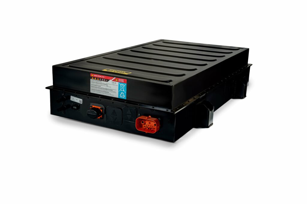
The pack combines high-performance battery modules with NMC cells, the battery disconnect unit (BDU), control electronics, and high-efficiency module cooling plates and manifolds. The BDU assembly contains the main contactors, precharge circuit, fuses, gas sensor and the String Control Unit.
The enclosure provides a variety of mounting options, ventilation, electrical and coolant interfaces, manual service disconnect with half-pack fuse, and a port for optional, customer-specific auxiliary gas sensing.
As heavy-duty applications vary from trucks to mining equipment and excavators, vehicle assemblers have a wide range of requirements, so the packs need to offer long-end (side), short-end and corner mounts to cater for various vehicle configurations, including placement underneath truck and bus cabins (inside or outside the rails), on top of vehicles or in rear racks.
After mechanical installation, high-voltage connectors, a single data connector and two coolant ports link to the rest of the system. A Battery Management System (BMS) interfaces with the vehicle’s CAN network to control packs in parallel. The latest BMS systems can control up to 24 packs with one Master Control Unit.
The BMS String Control Unit provides safety monitoring, diagnostics and control of the system. Its primary function is to maintain the lithium-ion cells within their safe operating range, regardless of the demands placed on them. This gives the BMS the ability to accurately predict operating situations with the potential for creating over- or under-voltage conditions, as well as adjusting performance for high or low temperatures, and reacting quickly and safely to prevent unsafe combinations from occurring.
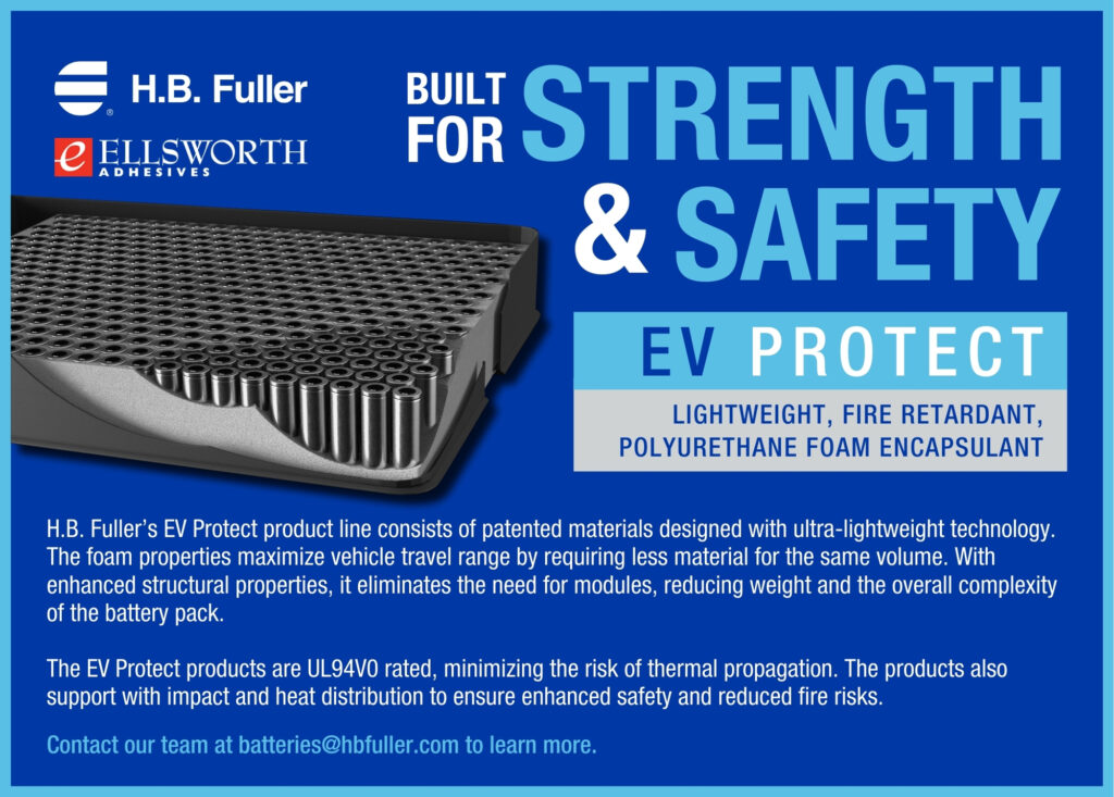
With hundreds or even thousands of lithium-ion cells in a heavy-duty vehicle, mitigating the risk of thermal runaway is key. This can be achieved with high-temperature barrier materials, software algorithms to find defects and early gas detection. Containment measures ensure any potential thermal incidents are localised within the pack, preventing damage to the rest of the system.
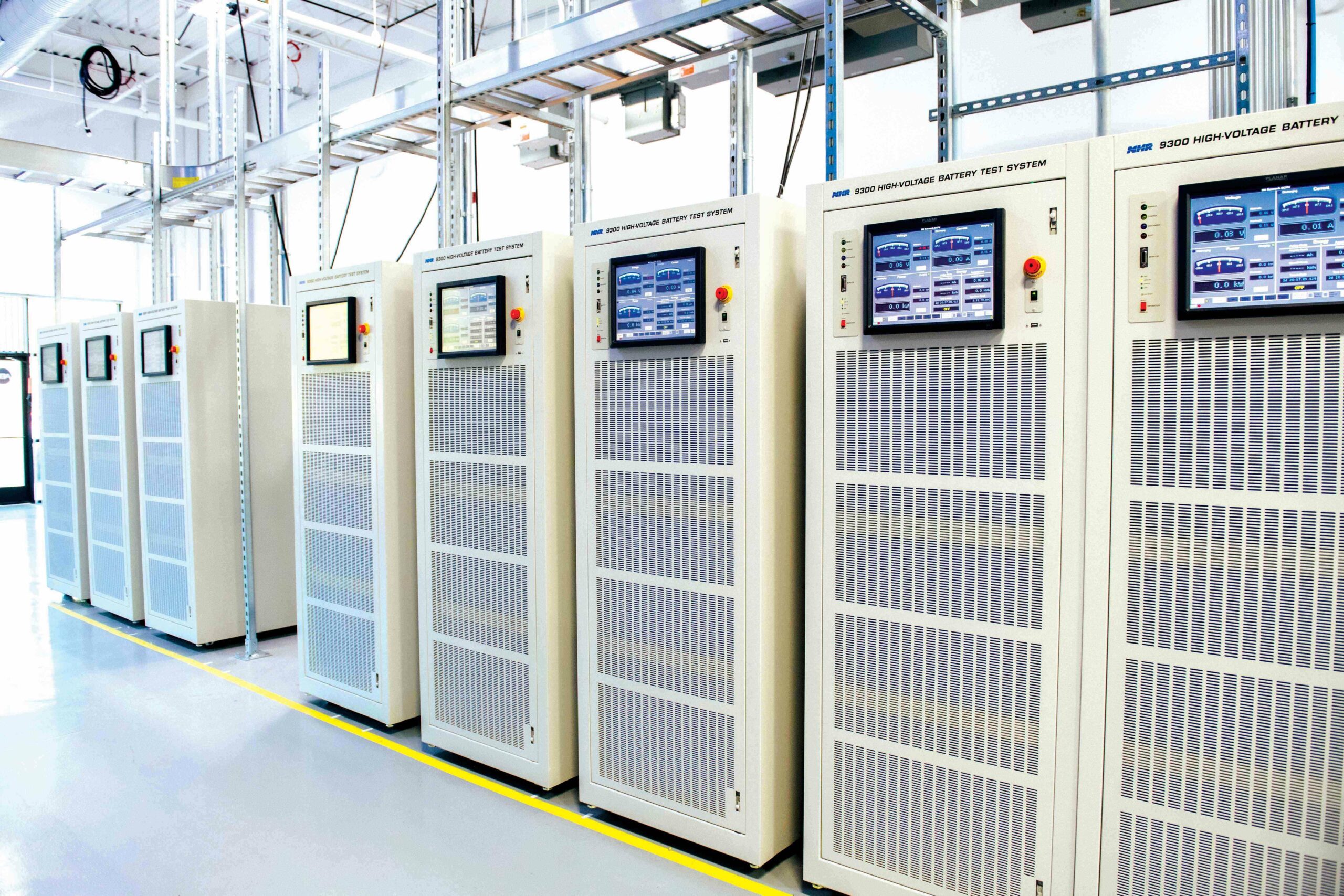
(Image courtesy of Freudenberg)
Cell characterisation
From a performance standpoint, it is not the form factor of the cell but the quality that matters. Detailed characterisation is needed to ensure the quality and consistency of cells, making sure one poor-quality cell does not pull down the performance of the others in the module, or even the overall pack.
This has led to the creation of an architecture, rather than a single module, which uses three modules with varying serial and parallel configurations to provide different voltage and energy combinations, but these can all be built on the same lines within a 3 ft envelope that gives flexibility for production.
One advantage of this architecture is that another type of battery cell can be used in the module for a higher-power version in the same 2170 format; or the architecture can be modified for the 4680 or 4695 form factor in the future.
The architecture with NMC 2170 cells has two bricks of cells with a cooling plate in between. Water glycol runs through the cooling plate to remove heat, and every module has its own plate.
LFP cells tend to be prismatic and there are different formats, from the narrow and long Euro MEB form factor to a tall version for China, and the Blade form factor used by some Chinese car makers.
Going to a prismatic cell changes the module design, and allows a battery pack to fit between the frame rails. For Class 6 trucks, it is 650 mm, and the LFP prismatic cells allow a thinner pack to fit between the rails as it can use a simpler cooling system in the 850 mm rails of Class 3 trucks.
An LFP battery system could have a bottom cooling plate integrated into the structure of the pack to optimise cost and reduce size. This would use an aluminium base, and composite or sheet moulding compound (SMC) or fibreglass cover.
One of the big differences for heavy-duty battery packs is that all the mechanical structure is in the pack rather than being part of the chassis.
While swappable batteries are an interesting technology gaining traction in mining applications, many heavy-duty vehicle designs put the batteries in two, three or four locations, partially to spread the weight but also to fit into the frame-based chassis originally developed for diesel engines. This limits the ability to remove a battery pack easily for recharging.
(Image courtesy of American Battery Solutions)
Modular packs
Modular design enables customisable battery pack dimensions that can be easily configured to megawatt-per-hour scale systems for a variety of heavy-duty uses. With the architecture for a major truck and bus maker, up to four packs can be configured in series, and 16 connected in parallel, to provide a wide range of capacity and packaging options for different types of EVs.
There are different form factors for different vehicle applications. One has a width of 860 mm and a length of up to 2808 mm, and can contain up to 123 kWh of energy storage per pack with an output voltage up to 1200 V.
For commercial vehicles with space constraints that call for a narrower battery pack, there is one form factor that can fit between the frame rails of a vehicle chassis with a width of 620 mm and hold up to 125 kWh of energy.
Safety features are key for heavy-duty applications, including cell-level passive propagation resistance (PPR). With PPR, on the rare occasion that a single battery cell failed with a thermal event, it would not spread to neighbouring cells.
Instead, the defective cell would remain isolated from the rest while the pack architecture allowed for proper venting away from the occupant cabin and doorways. This approach also enables a slower, more controlled release of energy over a longer period of time.

(Image courtesy of Sandvik)
Module construction
The construction of a modular battery pack typically involves designing individual modules that are self-contained units, each containing a set of lithium-ion battery cells and associated electronics. These modules are connected in series or in parallel to form the larger battery pack that powers the EV.
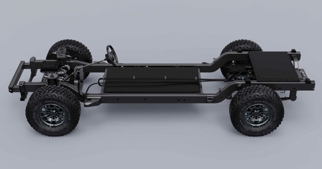
To increase the structural rigidity of an EV chassis, the design replaces traditional vehicle structures with a dynamic battery pack. This involves designing the pack as a structural component of the vehicle, rather than as a separate unit mounted on top of the chassis. By doing so, the battery pack can help to increase the overall stiffness and strength of the vehicle’s frame.
One approach to integrating the battery pack into the structure of a vehicle is to use the individual modules to create a platform that runs the length of it. This platform is essentially a flat, rectangular structure that contains the battery modules and serves as the base of the vehicle. The rest of the components, such as the body and interior, are built on top of the platform.
By using the battery pack as a structural component in this way, the vehicle’s weight can be more evenly distributed across its length and width, which can help improve handling and stability, particularly in high-performance EVs, where weight distribution is critical.
In addition to improving the structural rigidity of the EV or reducing costs, integrating the pack into the chassis can improve the packaging efficiency of the battery cells and reduce the complexity of the vehicle’s design, as there are fewer components to integrate and connect.
(Image courtesy of Alpha Motors)
Mining measures
One mining truck features a trolley pantograph connected to an overhead catenary line, which is a concept highly suitable for long-haul ramps. The electric trolley line gives additional assistance to the battery-electric mine truck on the most demanding stretches up-ramp while fully loaded, enabling further reach and battery regeneration during drift, which increases productivity drastically for a mining operation.
A full-scale, autonomous, electric trolley system is being installed in the Rävliden mine, Sweden, with four such systems, operating at a distance of 5 km and a depth of 750 m.
(Image courtesy of Freudenberg)
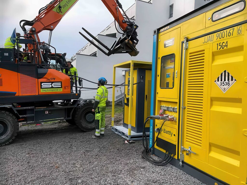
Swappable packs
An alternative is a swapping system, which takes about five minutes, enabling the operator to stay in the cabin and removing the need for heavy mine infrastructure. This is not a trivial task. The LFP battery pack measures 1800 x 2130 x 1680 mm and weighs 8,260 kg, with a capacity of 576,000 Ah.
Batteries are swapped quickly, without needing overhead cranes or forklifts. The operator drives to the swapping bay, lowers the depleted battery and retrieves a fully charged one.
The 320 kW charging and water-cooling units are the same size, allowing for a variety of configurations to fit any mine, making it easy to relocate and handle multiple operations simultaneously. They are moved by forklift.
Electric surface drilling rigs have long depended solely on a tethered cable as the power source. A battery-electric surface concept combines battery power with a 1 kV cable.
The battery pack provides power for up to one hour of drilling, or up to seven hours of tramming. The battery is primarily intended for tramming and drilling individual holes, while the bulk of a pattern is carried out via power from its 180 m tethered cable.

The battery allows greater freedom and flexibility, and more efficient use of time, as the rig can drill immediately while the cable is being set up. The cable tightens itself automatically, according to the direction in which the rig is moved, and it is wound on a single layer, which enables a thinner, more manageable tether. The 1000 V operating voltage helps to enable a lighter cable.
Another removable battery approach converts existing Class 8 diesel engine trucks due for a rebuild or replacement, swapping the engine with a new electric motor and a removable battery pack at a comparative cost of rebuilding an existing diesel motor.
As the batteries are not permanently fixed to the truck, they can be removed in four minutes, and charged at a Charge and Change Station. This station is designed as a three-way system with a grid-to-battery connection, battery to battery, and battery to grid, enabling renewable energy to be fed back into the grid, helping to balance and minimise surges and outages. The packs have been designed with an eight-year lifetime, but they are upgradeable to newer battery chemistries.
Removable batteries
A modular battery system for an electric truck improves performance by adding an additional pack, mounted on the rear of the chassis, providing extra power, and improving range and acceleration.
The pack is designed to be removable, easily replaceable and it can be charged using renewable energy sources. The modular pack is electronically connected to the main battery pack through a control unit that manages the flow of power between the two.
This design can improve the truck’s traction, stability, weight distribution and handling, and it can also be configured to optimise vehicle dynamics and driving performance.
To remove a modular battery pack from an EV, the operator must follow a simple process.
First, the electronic connections between the modular battery pack and the control unit must be disconnected, which is typically done by unplugging a series of connectors linking them. Then, the pack can be physically removed from its mount on the rear portion of the chassis.
Using a modular battery pack can reduce downtime and maintenance costs. This is crucial in applications where the truck is used for heavy-duty tasks, such as hauling cargo or towing.
Rather than having to replace the entire main battery pack, which can be costly and time-consuming, the modular one can be quickly and easily replaced in the field, without the need for specialised equipment, allowing the truck to get back to work as soon as possible.
The ability to charge the modular battery pack using a solar panel or other renewable energy source can also provide significant cost benefits, reducing reliance on traditional power sources such as the grid.
Mounting a modular battery pack on the rear of an electric truck chassis can benefit vehicle dynamics and driving performance. This added weight on the rear end can also improve balance and stability; the truck is less likely to oversteer or understeer when cornering, which can enhance overall handling.
Additionally, this can provide greater traction, particularly when the truck is hauling heavy loads, helping to reduce wheel slip and increase grip, which can enhance acceleration too.
Another benefit of having a modular battery pack mounted on the rear of the chassis is that it can improve weight distribution. With a more evenly distributed weight between the front and rear axles, the truck can provide more stable and predictable handling, particularly at high speeds or in adverse weather conditions.
In cold weather, charging times can increase due to the lower efficiency of the battery, but a modular pack can be charged separately and then added to the main pack, reducing this and improving the overall efficiency of the EV. It can also include a built-in battery heater to warm it before use.
The modular system can be easily scaled up or down, allowing customers to add or remove battery modules as their needs change. This can be valuable for commercial EVs, as it allows for the addition of capacity if the vehicle is used for longer trips or heavier loads.
MW charging connectors
The latest standard for megawatt charging connectors focuses on Class 6, 7 and 8 commercial vehicles, but could easily be used for buses, aircraft or other large battery electric vehicles (BEVs) with huge battery packs and the ability to accept a charge rate over 1 MW.
The Megawatt Charging System (MCS) uses a single, conductive plug that supports up to 1250 V and 3000 A, and it is bidirectional, allowing vehicle-to-grid (V2G) connections.
The positioning of the connector on a truck is key, and this has been specified on the left side at roughly hip height, and it can be automated. A survey among vehicle manufacturers within the MCS subgroup resulted in inlet positions of between 2 m and 4.8 m, measured from the front of the vehicle.
While heavy-duty equipment has large battery systems and needs high power chargers, the stress on the pack is not necessarily significant. For example, the latest electric buses have eight batteries with 880 kWh of storage, but with an 800 kW or megawatt charger that is a 1 C-Rate, which is low. By comparison, a car with an 80 kWh battery pack on a 350 kW charger has a 4.4 C-Rate.
Fast chargers can be used with LFP and NMC heavy-duty packs, but have been more suitable for LTO chemistries, with higher power packs for tractors and construction equipment, which can support 10-40 C-Rates.
MCS also offers more robust communication, reducing downtime related to charging failure. Commercial vehicles have specific driving patterns with mandated break times. These regulations state that drivers must take a break on occasion during their drive cycle; the exact time varies by location, but the aim is to fit the charging times into normal breaks in the duty cycle.
Accessibility also has to be considered when installing MCS chargers in public infrastructure as they need to be accessible by large commercial vehicles requiring drive-through.
The communication topology is an important part of the MCS specification. Following the OSI seven-layer model, one important part of the work involves defining a physical communication layer. Charging systems deployed around the world presently use physical layers with differing technologies, each with their own pros and cons.
The physical layer of MCS natively supports TCP/IP-based communications to implement the ISO 15118 communication standard easily without the need of additional, complex middleware.
ISO 15118 is the well-established standard, with many subgroups working on different implementation details. ISO 15118-2 has been in use throughout the charging industry for many years, but it has some limitations due to inconsistent interpretation and implementation.
Other DIN and SAE protocols have also been used for years, but they have even more limitations. This has led to ISO 15118-20, which has been in use since 2022 as a complete and robust, globally available protocol.
The maximum temperature limit of the pin/socket contacts for MCS is set to 100 C due to the following reasons: adequate testing results show that even at 100 C contact temperature, the permissible surface temperatures defined in IEC 62196 and UL2251 are maintained; increased ageing is less of a concern with the materials and surface treatments available now; and the current standards necessitate the use of composite materials with temperature ratings exceeding 105 C.
The existing limits of IEC 62196 and UL2251 are based on old, material limits that specified a maximum temperature limit of 90 C; 100 C was agreed as a compromise to provide a design margin below the materials limit of 105 C.
Commonly used composite plastics can be found in high-temperature grades with relatively higher working temperatures. These grades of plastic are not prohibitively expensive and would allow for a contact temperature increase while remaining within working limits.
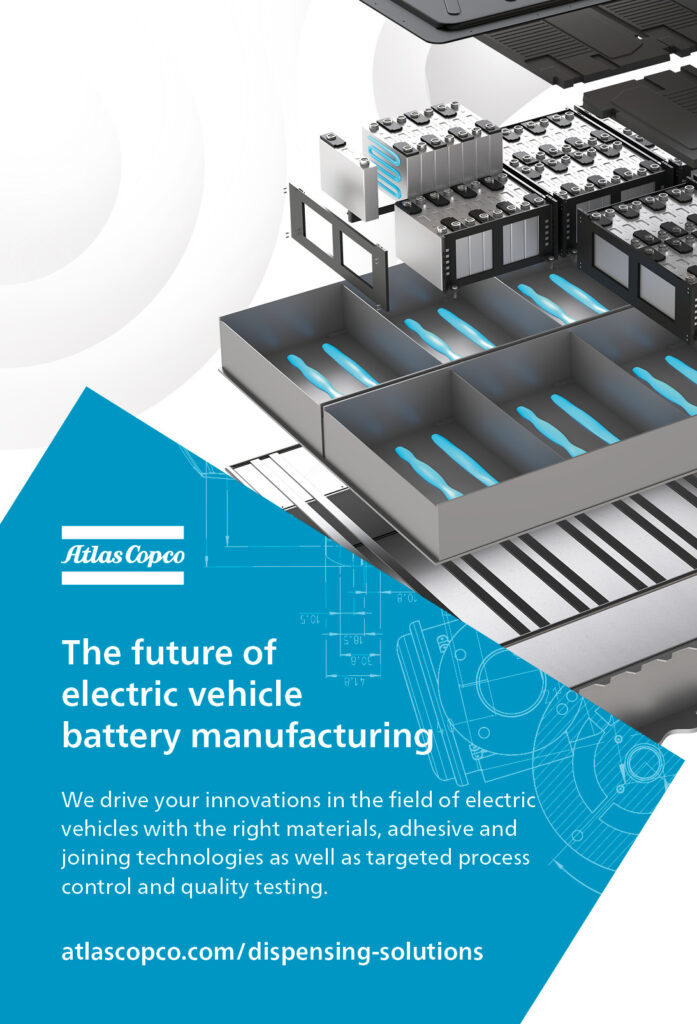
(Image courtesy of Atlas Copco)
Short-circuit protection
The larger battery packs of heavy duty systems mean that the prospective short-circuit currents from multiple battery packs, as available at the vehicle inlet, should be limited by the vehicle to a peak current of 70 kA and 12 MA²s.
The most important factor for the voltage is to support as many vehicles as possible while balancing this with the total operating range. Alternatives were considered, such as reduced operating performance with higher/lower voltages needed due to unique operating modes or battery cell chemistries.
MCS should use a minimum voltage of 500 VDC and a maximum voltage of 1250 VDC. While this will not cover all of the possible use cases of every vehicle type, this is expected to provide a good compromise between operating voltage range and vehicle coverage, with the connector designed for 1500 VDC.
The recommended MCS retention is based on the lessons of the consumer’s CCS connector. The MCS interface includes an electrically activated/actuated lock to ensure the connector remains engaged with the inlet during normal operation, and in case of a short circuit.
This electrically activated retaining means shall provide feedback to the EV and be controlled independently of the buttons or switches used for normal user-requested shutdowns or emergency shutdowns. The retaining means shall be integrated into the inlet side of the MCS coupler on at least one location, and up to three. The lock shall have a pin or slot design that operates consistently in all expected operating conditions.
The distance from the SECC to the EVCC is critical for stable, high-level communications. As communication cable lengths of up to 17 m (15 m outside vehicle plus 2 m inside vehicle) are expected, and the site layout and charging connector locations also consider a maximum cable length of 15 m, CharIN recommends 15 m at most.
For liquid-cooled cables, it is recommended to keep lengths as short as possible to avoid excessive performance requirements on the cooling system and manual handling of the cable. The charging inlet position on heavy duty vehicles and the charge-bay layout should therefore be standardised.
MCS is a newly developed charging interface and system that will continue to evolve as it becomes increasingly more technically detailed.
Acknowledgements
With thanks to John Warner at American Battery Solutions and Felix Nelius at Freudenberg FEPS.
Suppliers list
American Battery Solutions
ABB
Alpha Motors
Atlas Copco
Dannar
Electrovaya
Eleo
Freudenberg e-Power Systems
Janus Electric
Proterra
Proventia
Sandvik
Webasto
+1 248 462 6364
–
–
+1 949 393 0548
+1 765 216 7191
+1 905 855 4618
+31 492 25 10
+49 6201 80 0
–
+1 864 438 0000
+358 50 4088 142
+46 8 456 11 00
+49 898 57 940
www.americanbatterysolutions.com
www.abb.com
www.alphamotorsinc.com
www.atlascopco.com
www.dannar.us.com
www.electrovaya.com
www.eleo.tech
www.freudenberg.com
www.januselectric.com.au
www.proterra.com
www.proventia.com
www.sandvik.com
www.webasto.com
ONLINE PARTNERS


