


")


")

The Battery Show Europe show report
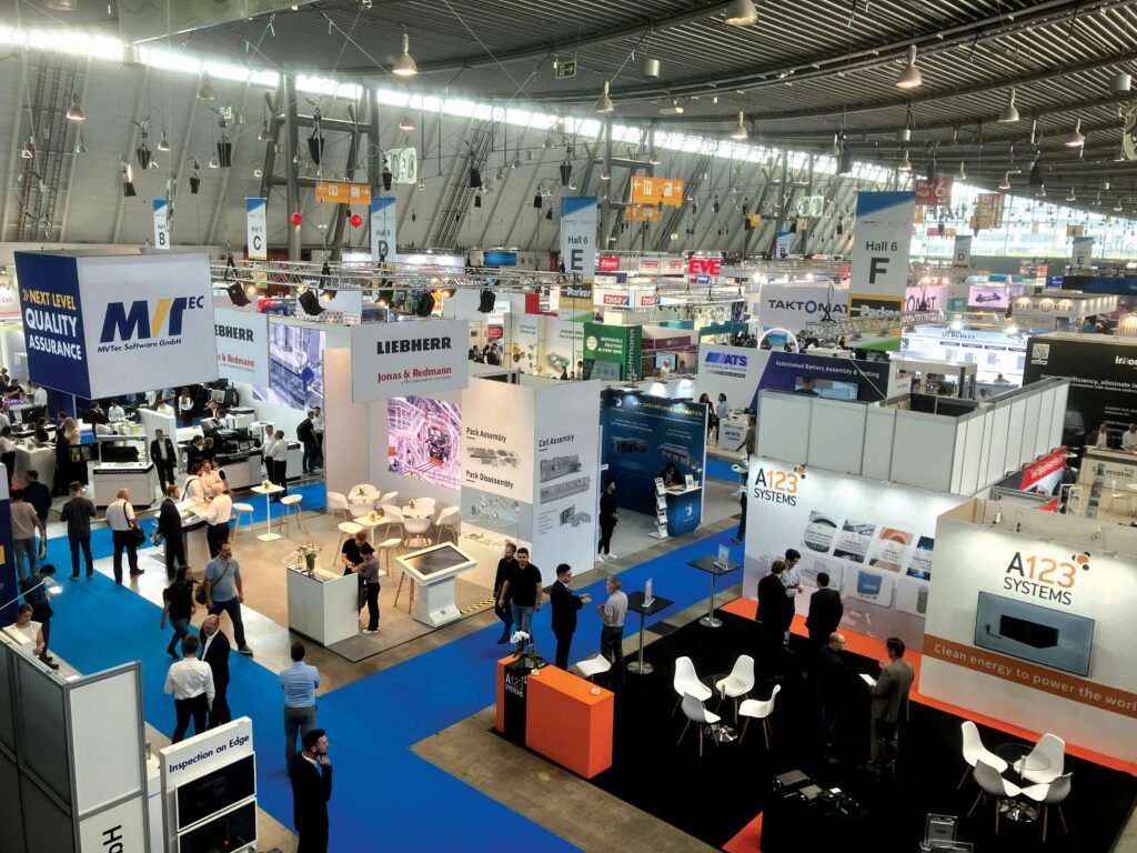
(All images by Peter Donaldson)
Cool runnings
Peter Donaldson highlights some hot discoveries at The Battery Show Europe
In June, Stuttgart Messe played host to The Battery Show Europe, an event that highlighted advanced manufacturing and developments in easing the dismantling of battery packs at the end of their first life, as well as innovative battery architectures, vehicle designs and componentry.
Henkel presented its electrical de-bonding technology for battery adhesives to facilitate dismantling. Expert in sustainable batteries and adhesive technologies, Philipp tho-Pesch explains that the growing use of structural adhesives in cell-to-pack and cell-to-chassis designs, while providing great stiffness and strength, makes disassembly impractical, creating the need for a reliably controllable de-bonding capability.
“The de-bonding technology that we are highlighting here works with an electrical trigger,” he says. “We apply an electrically de-bondable adhesive between electrically conductive surfaces. For application and bonding, this has similar properties to structural and thermally conductive adhesives, but if you want to dismantle the battery you apply a current to the bond lines, and within moments you can easily de-bond individual cells or, more likely, modules or stacks.”
The de-bonding capability results in a clean adhesive fracture pattern and allows for manual or automated disassembly.
“The application of a voltage will create a weak boundary layer, and then you will be able to separate the bonded parts,” tho-Pesch says. “You will be able to peel off the adhesive and have clean substrates afterwards, which will allow for re-bonding.”
He also emphasises that the process, which employs direct current, is not just for use by OEMs at factory level, but can also be done in local repair shops.
“What you would need is a traditional, industrial power source by which you can independently control current and voltage to the settings needed for successful de-bonding,” he explains.
To avoid unwanted de-bonding, the process is designed to work only at voltages and currents much higher than could be present on the bond lines in a battery, he adds.
The electrically de-bondable adhesive is at an advanced stage of development and Henkel is planning to bring it to market in 2025.
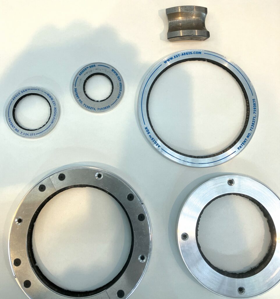
Electro Static Technology showed off its Aegis shaft grounding rings, which protect e-machine bearings from damaging electrical arcing that can take place in motors controlled by inverters.
The problem is that control schemes such as pulse-width modulation (PWM) convert DC into AC by rapidly switching between positive and negative voltages, which generates a common-mode voltage that appears equally on all three output phases relative to the ground.
“The motor behaves as a capacitor because of the different potentials on the stator and the rotor, and the tiny air gap between them,” Michael Firl explains.
The fact that inverters switch rapidly between positive and negative voltages exacerbates the problem by causing a very high rate of voltage change (dv/dt), generating strong electric fields that cause greater capacitive coupling.
“For example, a positive voltage on the stator binds some of the negative charge on the rotor, leaving the rotor with a net positive charge due to this capacitor effect.”
When the shaft voltage becomes high enough, it discharges through the bearings in the motor housing, resulting in micro-arcing between the balls and the race of the bearing, Firl explains. He adds that localised melting creates a fluted wear pattern around the bearing race.
Aegis grounding rings solve the problem by creating a current path from the shaft to the housing that bypasses the bearing. Inside the alloy ring are flexible, conductive fibres that are permanently in brushing contact with the shaft.
The company is also working on a new version designed to run in bearings lubricated by oil mist or an oil flow using additional fibres of a different material to maintain contact through the oil film.
Grounding rings can be retrofitted, but are increasingly incorporated at the design stage, Firl says.
Dürr, Grob and Manz displayed a large, comprehensive model of a 10 GWh factory that includes every battery production process from mixing of anode and cathode materials to the formation of completed batteries.
The companies have formed a loose partnership to offer customers such factories with fully integrated and digitalised processes that provide benefits such as improved yields and reduced scrap rates, according to Dr Hannes Schmüser, president & CEO of Dürr’s Clean Technology Systems division.
“We can provide complete factories as turnkey suppliers,” he says. “The important thing is not just to have put together machines from different companies, but to have fully aligned interfaces in a seamless concept.”
This concept includes digitalisation via a manufacturing execution system/manufacturing operations management (MES/MOM) solution for the whole factory, with all machines linked through programmable logic controller (PLC) data blocks, he explains.
This close integration is key to the reduction of scrap rates and it is a differentiator for the partners, says Schmüser. “Customers working with Asian equipment suffer from high scrap rates of 20-30% or more, and scrap reduction is one of the most important ways to raise overall equipment efficiency (OEE) and total cost of ownership.”
The equipment depicted in the 10 GWh concept factory includes electrode mixing, coating, drying, solvent recovery, calendaring, slitting, stacking (for prismatic cells), electrolyte filling, module and battery assembly, formation and ageing. All equipment from coating to cell assembly comes from Dürr, Grob and Manz, but Schmüser emphasises that customers can specify equipment from other suppliers, which the partners will then integrate.
Schmüser adds that automation is very important to the concept, and the company is now working on material-handling technology, such as autonomous guided vehicles (AGVs).
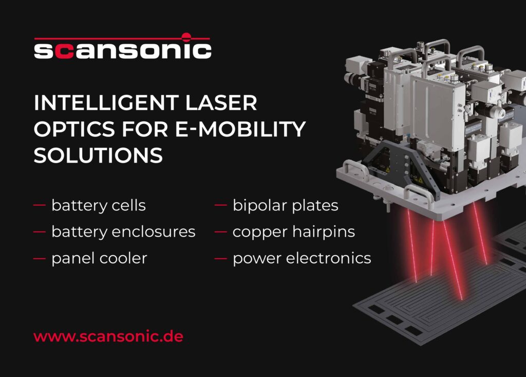
Scansonic promoted its fast component-welding technology, which it developed to meet the growing need for rapid, high-quality joining of large and differing metal parts in big volumes, says Pravin Sievi.
Customers want to move on from welding speeds of around 3 m per minute (m/min) up to 100 m/min, which is more than any single welding head could reasonably achieve.
Sievi gives an example of a 2 m x 1 m sheet of aluminium to be used in a battery cooler. “There are 100 m of laser welding on it and every millimetre must be sealed tight.”
The requirement was for a 30 m/min welding speed, but aluminium is sensitive to hot cracking and the power needed to achieve that speed with a single head would produce a lot of heat. Sievi explains, however, that Scansonic found a “process window”, allowing them to weld at 15 m/min with the standard welding head and laser source, achieving speeds of 30-60 m/min by arranging the heads in an array.
Increasingly, EV and battery applications call for the joining of dissimilar metals, such as copper to aluminium, nickel-coated copper to steel, etc. “Such applications are very complicated to weld because there is no intermetallic combination of those alloys, so they join by mechanically interlocking with each other, like a zip,” he adds.
Scansonic joins components of the same material using multi-mode lasers with spot diameters of 150-200 microns; joining dissimilar metals requires single-mode lasers with much smaller spots of 60 microns.
“We can process both multi- and single-mode lasers without changing anything in terms of what the customer sees. We use the same focal distance, the same shape of head, the same software functions, and so on,” he says.
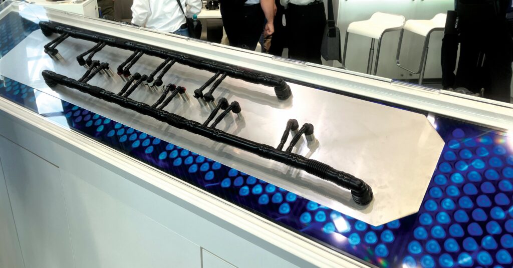
Voss showcased its new immersion cooling system for batteries, which includes dielectric (non-conductive) oil-based coolant and conductive, polymer fluid management components.
While it is essential that a coolant that comes into contact with conductors within the battery is non-conductive to prevent short circuits, it is also important that the other components are conductive to prevent the build-up of electrostatic charges that could create pinholes when they discharge, causing leaks, explains account manager Joerg Schormann at Voss Automotive GmbH.
“The oil is very thin, and therefore it is very important to have 100% sealing in the cooling circuit and perfect connections,” he says.
Voss has tested a wide range of dielectric cooling oils and is confident that it has a reliable immersion cooling technology.
The fluid management system includes thermal management modules, which contain pumps and valves plus installation-space-optimised connection technology and pre-formed lines. These are made of a special polyamide matrix with carbon fibres in the mix to give the material its electrically conductive properties.
Besides finding a material that works completely safely with many different oils, there were system-level performance and packaging challenges to overcome, Schormann recalls. A lot of computational fluid dynamic (CFD) work had to be done to ensure an adequate flow rate through the cooling system to match the fluid’s heat capacity to the overall heat-transfer requirements.
All these requirements had to be met in the small volumes typically allowed in EV bodies for the thermal management system components. “Finding space in cars is always a challenge.”
“High-performance vehicles form the initial target market.” Schormann adds.
Lead Intelligent discussed the company’s all-solid-state battery production technology. Dr.-Ing. Hannes Weinmann, head of pre-sales and new technology exploration at the company’s German division, covered various process steps, including solvent-free and solvent-less film fabrication technologies such as dry mixing and dry coating, as well as new assembly line equipment for solid-state batteries.
“While many of the processes are essentially the same for both conventional and solid-state batteries, there is one difference that has major implications for the safety precautions required during battery assembly. In solid-state batteries, the cell is activated immediately after the anode and cathode layers are stacked, creating a voltage that necessitates careful handling to avoid short circuits” he emphasizes. “This contrasts with conventional batteries, where activation occurs later in the formation process, allowing for easier handling of cell stacks.”
Dr.-Ing. Weinmann explained further that solid electrolytes are introduced into the battery in two ways: first, during the mixing process for the cathode, where they blend with active ingredients; and second, as a layer between the anode and cathode, replacing the conventional separator. “This layer not only serves as an insulation barrier but also facilitates ion transfer between the electrodes. It is crucial to address interface issues between layers and particles, ensuring the solid electrolyte is resistant to dendrite formation and has high ionic conductivity.”
Additionally, Dr.-Ing. Weinmann highlighted the importance of maintaining a clean room environment to control impurities and humidity, reducing the risk of contamination and short circuits in water-sensitive materials.
The technology is now advanced enough for large-scale pilot lines, with the first customer based in Asia, Dr.-Ing. Weinmann says.
Lead Intelligent offers integrated, automated smart manufacturing solutions, covering all stages from production planning and raw material processing to assembly, testing, final packaging, and battery recycling.
Full integration enhances efficiency and product quality using advanced digital technology, says the company, which serves many of the largest automotive, renewable energy, and technology firms.
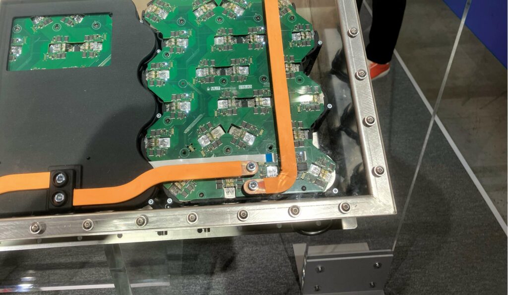
Handtmann Systemtechnik showcased its developmental, inverter-eliminating AC battery technology at the show. While an electrochemical cell is a fundamentally DC device, if you divide the switching capability normally found in an inverter among the connections to each and every cell, along with the appropriate control logic, the battery will deliver the AC that most EV motors need, and accept AC during charging as well, also eliminating the need for an onboard charger, explains systems development engineer Marc-Andre Gruenewald.
“It is based on technology that can reach out to every single cell, and disconnect and reconnect it to generate an AC waveform at the voltage you need,” he explains.
Gruenewald adds that the technology can also act as a multi-level inverter, putting out a nearly sinusoidal waveform that offers higher efficiency and power quality, and longer cycle life.
Charging “with frequency” is a big advantage for longevity, Gruenewald says. “You don’t have a constant voltage, and this is very good for the chemistry; you don’t produce crystals inside the cell, and it boosts the cycle life. You can use a regular AC or DC charger and just connect it to the battery, and it will charge.”
“We have one master PCB, which regulates all the currents and it manages the system, so there is no need to do any conversion, for example,” Gruenewald says. “One big challenge is that you need electronic components on each cell, so the bigger the cell is, the more easily you can implement this technology.”
Today, Handtmann is using 46 mm cylindrical cells, which can be connected from above.
“It’s nice, but the power you can generate with the system is limited by the amount of copper you can implement on the PCB,” adds Gruenewald.
The technology also allows battery designers to mix different cell chemistries to tailor them to each application. “You can use high power cells and high energy cells together, and regulate how much current, voltage and capacity you need.”
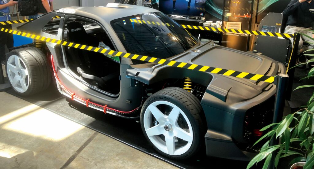
Roding Mobility presented the rolling chassis of the electric supercar it is offering to manufacturers worldwide. These include niche manufacturer ELegend, whose EL1 is a homage to, but not a replica of the Audi Sport Quattro of the 1980s. A limited edition roadcar, it is built on a new platform that the Roding team refers to under the project name Moneypenny, according to co-founder, CEO and James Bond fan Ferdinand Heindlmeier.
Specialising in advanced composite structures, e-powertrain and battery systems, Roding helps start-ups and established OEMs to create proof-of-concept vehicles and advanced prototypes. “We are a partner who can get vehicles on the road quickly. That means our customers are usually able to see their prototypes in just five to six months.”
The Moneypenny rolling chassis at the show was fitted with the 600 kW all-wheel-drive electric powertrain specified for the EL1, which is thought to weigh about 1,900 kg. The battery is a 400 V pack with a 90 kWh capacity, constructed from OEM modules containing prismatic cells with NMC chemistry.
“That’s state-of-the-art prismatic cell technology with a water-glycol cooling system. Also, the battery’s internal PDU [power distribution unit] is designed to handle up to 700 kW,” says Heindlmeier.
The battery has a C rating of between 6 and 7 at peak power and between 2 and 3 at maximum continuous power of 200-250 kW, which is enough to sustain a top speed of 250-270 kph, he says.

Power is delivered to the wheels through separate front- and rear-drive units, each integrating an inverter, a synchronous AC radial-flux motor, a single-ratio reduction gearbox and a differential. The motors and inverters share a cooling loop that is separate from the battery loop.
The control system has a distributed architecture, with one controller focused on the driveline, and a second on the cooling system and other peripherals.
The timescale for the EL1 is expected to be around nine months. “Typically, we can go from a design sketch to a road-approved prototype in less than 12 months for our customers.”
Comau presented several new capabilities in scalable battery manufacturing processes developed over recent years and its ongoing work on dismantling technology. One of these processes is cell formation, says Gian Carlo Tronzano, head of Comau’s Global Competence Centre for E-mobility.
Formation is a process that takes place towards the end of manufacture in which the cells are charged and discharged for the first time at tightly controlled current rates and temperatures to help form a stable, solid electrolyte interphase (SEI) on the anode.
Comau focuses on the process steps, but manages the whole turnkey operation. Tronzano explains: “We have developed our own formation chamber with different types of power electronics. We developed our own solutions for compression trays, OCV [open-circuit voltage] stations, the DCIR [direct current internal resistance] stations – everything is connected to the real process.”
The company has also been looking back along the value stream to battery dismantling. “We start with packs from cars being dismantled. There are many types of packs and they are very different from one another, so we need a solution that allows us to be flexible.”
Tronzano says Comau’s overall development process is ongoing, and it is currently working with car manufacturers who are sending them a variety of packs so they can discern efficient and flexible ways to dismantle them.
“The idea is to have visual systems that are able to recognise a new pack and where the fixing points are; then guide the operator to easily reprogram the automatic cell by using the right dismantling tool,” he says.
“We have tried to simplify this phase as much as possible through low-code software able to assist the technician, and define a list of operations and tools.
“An area in which we especially served customers is on the discharge of cells from production lines. Cell-manufacturing systems in Europe are producing a lot of scrap. So, for a European customer, we have supplied a discharging system. We open the scrap cell, we discharge it, we dry it and then we send it to the next steps.”
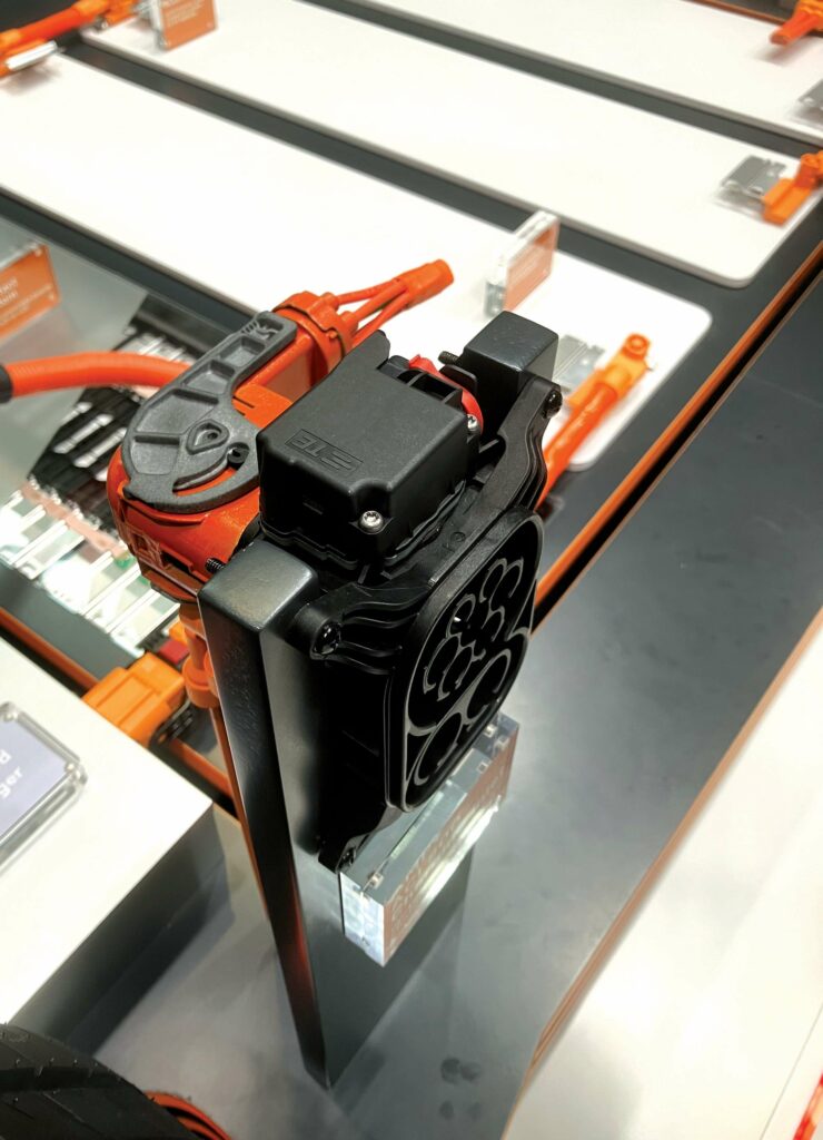
TE Connectivity talked about its new ACI 800 charging connector, which is designed to be modular and easy to integrate into a wide variety of different EVs, and, critically, serviceable that neither impact damage to worn contacts in a charging port leads to a very large repair bill, says Phillip Kowarsch, product manager, automotive e-mobility charging inlets.
“In previous product generations you would need to exchange the complete charging harness, and that would lead to a cost of about €3,000 to €4,000. Now you can dismount the connector and easily change only the inlet without touching the rest of the harness.”
AC and DC wiring harnesses can also be replaced independently of each other and of the charging connector.
Kowarsch emphasises that the ACI 800’s modularity provides the opportunity to manufacture it at scale, because the core power inlet will always remain the same, regardless of the vehicle to which it is attached. All adaptation to different installations and additional requirements, such as protective flaps and lighting modules, is done by changing the mounting bracket, he says.
Another key feature of the connector is the accurate temperature measurement required for boost charging with currents of up to 1,000 A. To achieve this, the N, L1, L2, L3 and DC positive and negative terminals on the connector’s printed circuit board assembly have individual temperature sensors, with only the PE/ground terminal not monitored for temperature.
The ACI 800 is also protected from water and other contaminants. “IP67 protection is really important to prevent any short circuits inside the inlet in case it is mounted in an area of the vehicle that could be exposed to water. Also, it’s important to know the degree of protection to evaluate the creepage distance in air,” Kowarsch says.
Creepage distance refers to the separation of two potentials, such as DC positive and DC negative. If the distance between them is too small, the current will jump the gap at high voltages and cause arcing. Contamination can shorten the effective creepage distance.
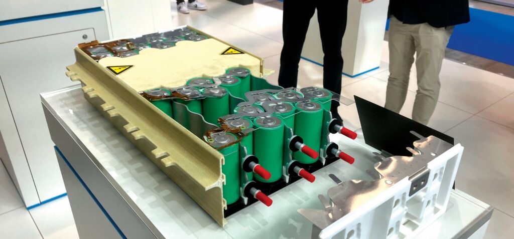
Rimac provided a close look at its flexibly configurable new Unimodule battery architecture. Based on 46 mm-diameter, cylindrical cells of various lengths with several cooling options, it is designed to support applications requiring density in terms of both energy and power.
“It is our latest battery technology that we are developing for automotive customers,” Ivan Babic says, indicating a cutaway model. “This is an example of how a module can look… It’s a technology that can be easily scaled for different customers, depending on the performance and energy they need.”
The model showed a configuration with the cell interconnections on the top, together with the flexible printed circuit (FPC) for the cell voltage-monitoring pick-up points; the monitoring board that handles both voltage and temperature measurements on one side. Free space inside the module housing is filled with a foam that provides structural strength and thermal insulation.
“One of the most important things is that we use the available space in the best possible way,” Babic says. “The cells are almost touching, and we have developed a technology that allows us to stop thermal propagation if one cell goes into thermal runaway; the mechanical design stops propagation to neighbouring cells.”
Rimac isn’t revealing exactly how this works, but it relies on the surrounding foam, on venting channels under the cells to direct gases and particles out of the module, and on the liquid cooling system.
The Unimodule can be configured with cooling plates at the top or bottom, or both, and/or with broad, flat cooling ‘snakes’. In the model, the snakes contact each cell on one side, but configurations that contact both sides are optional.
“It can be double-sided in a really high-performance pack, where you have to pull the cells’ temperature down very aggressively,” Babic adds.
Kautex presented a developmental lightweight two-phase immersion cooling system integrated into an electric golf cart to cool its battery, which is based on 21700 format cylindrical cells. “We decided to go for a two-phase system because it allows us to reduce the amount of liquid needed,” says senior sales and marketing manager Boris Meisterjahn.
“The cells are roughly 10% submerged. Therefore the weight of the liquid in the system is reduced to the minimum,” he explains. “The liquid starts boiling at about 30 C. And therefore, just from the heat released by the cell, it will change its phase from liquid to gas.”
In addition to reducing weight, the system also removes heat quickly enough for the battery to charge at a rate of up to 6 C-Rate. Theoretically, such a battery would charge in 1/6 of an hour (10 minutes). Part of the secret to this lies in Kautex’ expertise with composites and plastics, Meisterjahn says.
“We integrate very fine channels in the cell holder, and the shape of the channels allows us to initiate the phase change at a desired position.”
The dielectric fluid has a low global warming potential, he says, as the system is expected to lose enough to evaporation to require maintenance every two years.
Kautex is in pre-development discussions with two undisclosed OEMs. “It’s the first time we have really been talking about a true mass production application for two-phase immersion cooling.
“For us, the key challenge is integration with the car’s AC system. “We would like to combine the two to reduce overall energy demand and system cost for thermal management.”
ONLINE PARTNERS


