Battery cell manufacturing
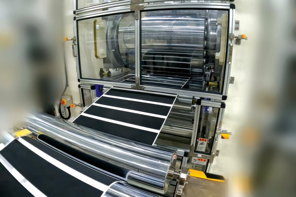
(Image courtesy of Honda Motors)
Building blocks
There are three major phases of activity for manufacturing battery cells, as Nick Flaherty reports
Moving from small coin cells that prove the performance of a battery chemistry in the laboratory to production is a big step. There are many different ways to construct a cell, and many techniques for both building and characterising the resulting battery.
The process of creating A, B and C samples of battery cells is key for continuous improvement to enhance the quality of cells, whether in a cylindrical, pouch or prismatic form factor. With new battery chemistries emerging and new approaches for building cells, particularly using solid-state materials, the process of battery manufacturing is a key area for e-mobility.
High production volumes in battery gigafactories are generally associated with economies of scale, and these are increasingly requiring highly digitalised and automated unique procedures that seek to combine various routes and complex sub-processes. The manufacture of safe, reliable batteries for e-mobility depends on this.
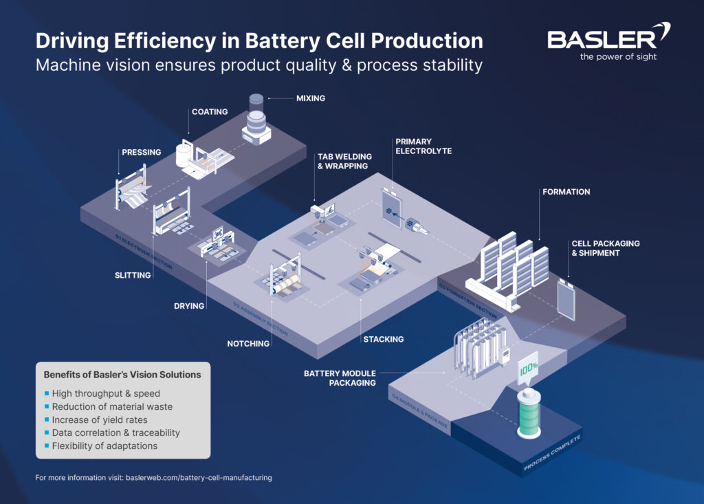
There are three major phases or blocks of activity for manufacturing battery cells: electrode manufacturing, cell assembly and validation.
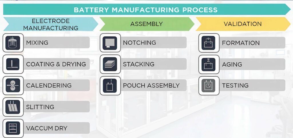
(Image courtesy of CIC energiGune)
Production process
Whatever the format (pouch, cylindrical or prismatic), the first step in manufacturing a battery is to produce the two covered layers known as electrodes. At this stage, it is vital to avoid contamination between materials, which is why gigafactories have two identical and separated production lines: one for the anode and the other for the cathode.
Generally, the anode is made of copper foil, coated with graphite. The cathode is composed of an aluminium foil, coated with a chosen chemistry; nickel manganese and cobalt for NMC cells, nickel cobalt for NCA cells or iron phosphate for LFP cells.
Four stages
There are four stages in the electrode-manufacturing process, as follows.
Mixing
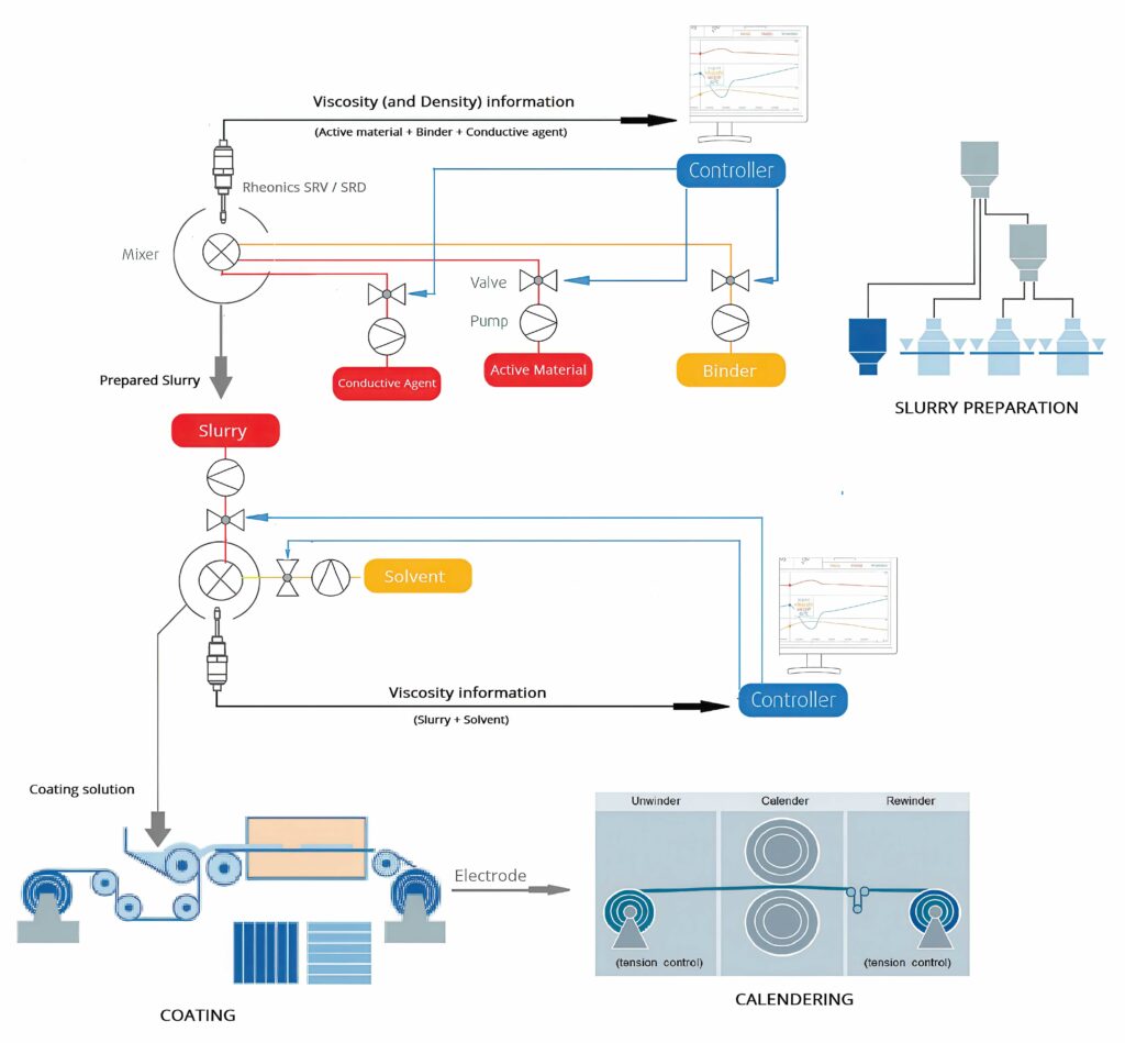
In the electrode production process, the first step is to produce a mix known as slurry, which has a significant impact on the battery’s final performance. This procedure is key for the subsequent bonding of the active material to the current collector, which will then transfer the electrochemical energy through the cell tabs.
The slurry is a mixture of powders (mainly active material) combined with a solvent (liquid) and a binder.
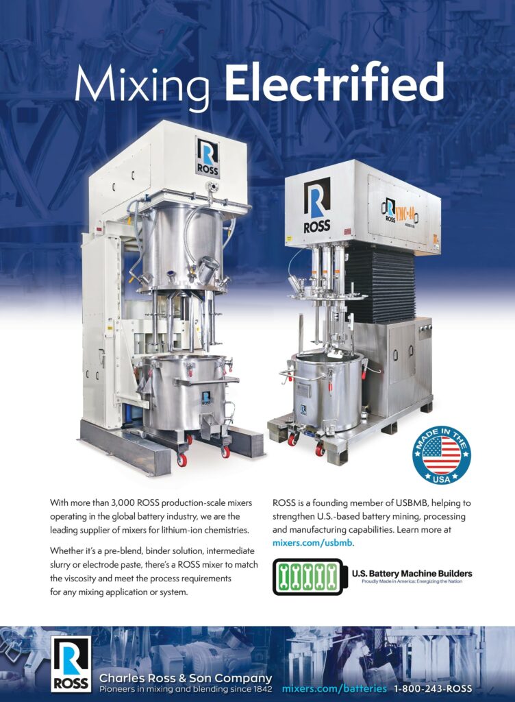
There are two types of equipment to produce the slurry: batch production (usually planetary mixers) or continuous production (which combines the basic dosing operations along the mixing chamber by means of automated, gravimetric feeding systems).
During the multi-step process, from raw materials to the final battery cell, the use of a twin-screw extruder can improve the critical step of the slurry.
Battery slurry production commonly uses a batch process to mix the active materials, carbon black, solvents, binders and additives in stirred vessels. This process is labour-intensive, bears the risk of batch-to-batch variations and requires production downtimes for cleaning.
Twin-screw compounding offers a continuous production process with precisely controlled material shear, heat transfer, material throughput and residence time. The twin-screw extrusion process offers high reproducibility, less cleaning time and high material efficiency.
The dispersive and distributive mixing of a twin-screw extruder enables a much more homogeneous cathode paste, compared with alternative batch-mixing in, for example, a dissolver. In return, this can lead to improved material properties.
As a result, using twin-screw extrusion can help to improve the classic production of cathode and anode slurries by moving from a batch that is challenging to scale up to a well-controlled, continuous process.
Extruders also provide excellent capabilities for solid-state battery (SSB) development (see below). An understanding of the rheological properties of an electrode slurry is necessary for a precise printing process to obtain batteries with high capacity and a high number of charging cycles.
Coating and drying
Once the slurry is produced, it is pumped through a piping system to the coating area, where the mix is printed on a metal foil that is unrolled to the coating head. There, the slurry is deposited, and the coated foil continues its process through a drying oven, where the solvent evaporates, leaving the active material attached to the foil and evenly distributed. Gradual drying is key to obtain a good-quality electrode, which requires ovens as long as 80 m.
This can also reduce the amount of solvent required, decreasing the energy required for drying the slurry by as much as 30% by producing almost-dry battery pastes.
The coating, which is applied on both sides of the foil, can be intermittent or continuous, depending on the cell size and format to be produced. In general, the width of the printed strips on the roll limits the dimensions of the cell and therefore directly affects the production capacity of the line.
Calendering
The next step in the manufacturing process is calendering, which acts as the finishing process for the coated rolls. Like the previous step, it is a roll-to-roll process, where the coated rolls travel through two heated rollers to compress the material, and thus ensure constant thickness, density and better adherence.
Slitting
Slitting is the first cutting process used to limit the foil to the size of the individual electrodes that will be required for final assembly. The rolls coming from the calendering process go through a bank of blades, which cuts them into multiple, smaller (daughter) rolls to fit with the final design.
Dry room assembly

Once the electrode-manufacturing phase is complete, the process moves onto the second phase of assembling the cells.
One of the most relevant aspects of this phase for lithium-ion and lithium sulfur batteries is that it must be carried out in a dry environment to avoid any humidity remaining in the electrode, which can lead to increased degradation and capacity loss.
This is carried out in a dry room with a dewpoint of -40 C, although even lower temperatures are required for more moisture-sensitive chemistries, such as NMC811 or lithium metal. At this stage, electrodes are cut and assembled in their cases. Although this process varies according to the cell format (pouch, prismatic or cylindrical), there are three main activities in this block.
Notching
For pouch cells, the next step is a cutting process that converts the coated rolls into individual electrode sheets.
The cutting machine (which differs for anode or cathode production) unrolls the foil and produces rectangular electrodes with an uncoated area left, which will be the tabs required later in the assembly.
The cutting process can be performed with two types of technologies: mechanical cutting, formed by a die with blades; or laser cutting. While the mechanical system usually reduces the cost, it requires regular sharpening and replacement of the blades. Laser cutting avoids direct contact with the electrodes and offers more flexibility.
Stacking
Once the sheets are produced, they go through a stacking process, which is usually the trickiest and often a bottleneck in cell assembly. This is the first stage in which the cathode and anode lines are combined. The goal is to alternately stack anode layers – separators and cathodes – while leaving the uncoated tabs exposed.
The typical method is Z-stacking, where the separator is folded over each electrode layer in a zigzag movement. Alignment is key, as misalignment can cause the electrodes to extend beyond the separator, creating a short-circuit once the cell is completed.
Another alternative is stacking through lamination. This method, similar to single-sheet stacking, joins two of the components together (separator/anode/separator) and these are later stacked inbetween cathode layers in an alternating manner.
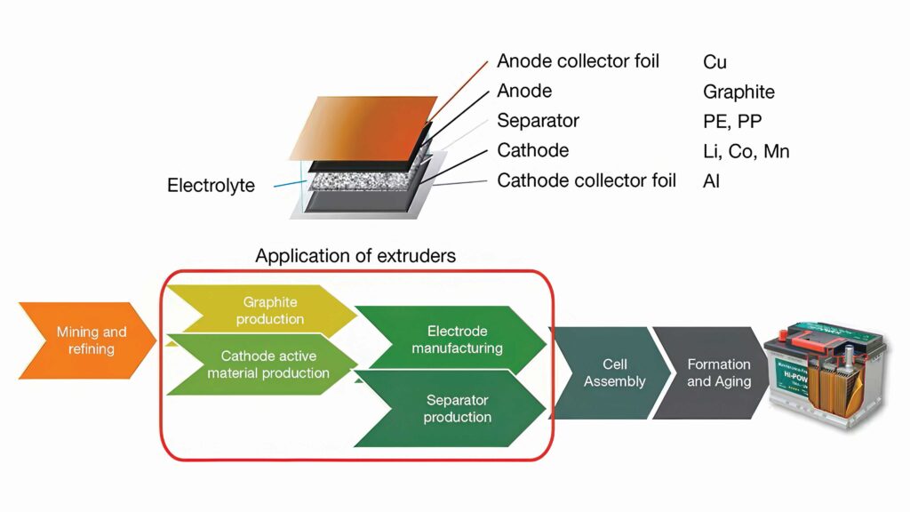
(Image courtesy of Thermofisher Scientific)
Pouch assembly
Once stacking is complete, the exposed electrode tabs must be attached to the main terminals through a welding process, which can be laser-based.
The cell is then placed into a preformed packing material and sealed, leaving an open edge for the electrolyte filling. After vacuum sealing the remaining edge, the product is left to soak for hours prior to forming, ageing and the test phase.
Sensors
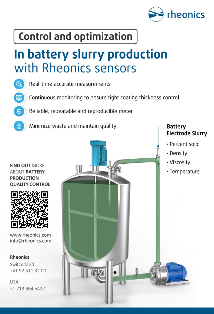
Sensors are key for an effective manufacturing process. The biggest thing we see is that manufacturers need to monitor the complete line, from the mixing to the coating, to provide continuous data.
At the start of the process, the anode or cathode slurry has the correct solid loading, as that is crucial for uniform coatings on the thin foil and ensuring its always of the same thickness.
This is best with continuous monitoring or inline, as batch sampling for quality control does not tie in well with knowing what happens during the process. Senors provide data points for the monitoring software to check conditions, and also to change the process and control the amount of liquid in the slurry in real time.
The inline viscosity sensors detect the homogeneousness of the slurry in a storage tank as it circulates to avoid sedimentation. The sensor is a balanced, torsional resonator that measures the product of density and viscosity, with the magnitude of the noise in the signal giving the dispersion.
The co-axial resonator twists the two ends of the sensors in opposing directions, cancelling out any torque when mounted on the equipment and making the sensors more stable in the mounts to provide more accurate measurements.
During the mixing of the slurry, unneeded agitation deteriorates and degrades internal structures with time. The target is to achieve thorough mixing of the constituents with maximum homogeneity and without the particles breaking up. Density control ensures correct material composition and constituent fraction, and viscosity control ensures consistency of the slurry preparation process.
A high-viscosity slurry causes problems in the coating process and poor dispersibility results in low film uniformity. Uniformity of the coating thickness and the layer density are crucial to guarantee control over the lifetime (recharge cycle time) and ion-transfer rate of the battery. Regulating the layer thickness enables a smaller battery to be created. Viscosity control is essential to achieve a homogeneous coating thickness and minimal deviations.
Battery slurry with higher viscosity increases resistance to sedimentation on standing and delivers a thicker electrode film on coating. The higher viscosity may also render the coating process harder to control, possibly leading to irregularity and variable layer density, which in turn brings about a variable ion-transfer rate and hence unpredictable battery life (and unpredictable recharge cycle time).
Electrode density has an effect on cycle performance and irreversible capacity loss in lithium-ion batteries. It needs to be monitored and controlled within appropriate ranges, based on the requirements in the calendaring process.
The density measurement provides the weight of the slurry, and the noise in the signal shows how homogeneous it is. There isn’t a direct relationship, but when the particles are larger the noise tends to be louder. These data points allow a real-time, stochastic curve to be generated from a measurement every second.
The viscosity of the polymeric binder solution affects coating performance. It influences the ease with which the powders are dispersed within it, the power required for mixing and the speed of application of uniform coating.
The Porous Electrode Theory (PET) suggests the relevance of positive electrode density on the overall performance of lithium-ion battery cells, validated by experiments. Cells with a high positive electrode density show a slightly higher discharge capacity at low current rates, but at high current rates the cells with a low positive electrode density give better performance.
A machine-learning framework uses the data from the sensors to build a model for the process, delivering 21 types of high-level data to the equipment suppliers. Many of these measurements are derived from the underlying stochastic curve and ML model, and are based on more advanced processing to integrate with the equipment data systems to control the process.

(Image courtesy of the University of Braunschweig, IPAT/Mattis Batzer)
Electrode coating
A second type of sensor uses the same resonant technique for measuring the thickness of the coating, as this is directly proportional to viscosity and speed. This measurement is vital as accurate control of the layer thickness improves efficiency and increases the lifetime of the cells, as the differences in the layers has an impact on the lifetime of the battery pack.
With a focus on the viscosity of the material being laid down, the system can compensate for any changes by varying the speed.
The next stage is the electrolyte filling, and that has a quality assurance and traceability issue.
All of the sensors generate traceability data with a QR code that provides the exact solid content and thickness that is essential under failure analysis, so you are not just banking on lab samples.
This can then be added into tracking documents such as a battery passport, which holds all of the direct data on the construction and validation of a cell, rather than using samples from a batch. This helps improve the overall lifetime of a battery pack by ensuring all the cells in the pack have a similar performance level.
This can be used for environmental measurements, such as raising an alert if moisture rises and the coating is affected. Measuring temperature highlights any changes in the slurry due to environmental issues through temperature-compensated viscosity. The sensors must have the resolution and stability to detect changes in moisture and temperature throughout the year, from day to night, so continuous monitoring is key, rather than a batch taken in the morning or evening.
Camera monitoring for Z-folding
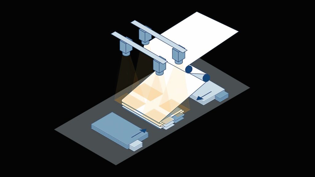
Pouch cells are manufactured by stacking electrode-coated cell sheets. In the Z-folding process, the pre-cut anode and cathode sheets are inserted into the separator foil from both sides. The separator foil is supplied as a rolled-up, continuous web material. This Z-shaped arrangement of the electrode sheets and separator foil gives the process its name.
The process is repeated continuously and up to 120 layers can be created. Once complete, the battery manufacturer seals the edges of the foil. Afterwards, the cell stack is wrapped with foil, the foil is cut off and the remainder is secured with tape.
Vacuum gripper systems pick up individual anode and cathode sheets, and alternately place them on the separator. Precise positioning of the electrode sheets and the separator is critical for the quality of this step.
Edge alignment must be as accurate as possible, with tolerances in the µm range: deviations of less than 200 µm are acceptable. High speeds add to the challenge of this process step: the electrode sheets are picked up and placed on the cell stack in less than one second.
Machine-vision systems, consisting of high-performance cameras and software, can ensure finished parts are produced correctly.
In the inspection process, four cameras check the correct positioning of the electrode sheets at each corner. The CoaXPress 2.0 interconnect standard ensures precise triggering in multi-camera systems and real-time data transmission at speeds up to 12.5 Gbit/s. The captured image data can be analysed using software to determine the exact stacking of the electrode sheets.
These vision systems need to be as compact as possible to fit into the production line and provide high-resolution images for the analysis. Those tools ensure the measured distances are output in calibrated metrics, and compensate for radial and perspective distortions caused by camera settings.
A model image can be used to define a measurement rectangle. During the process step, possible deviations in other acquired images of stacked anode and cathode sheets are output, either as coordinates if there is a rotation, or in metrics for distances to target edges to ensure stacking is within tolerance.
(Image courtesy of Basler)
Dry electrodes
Solvent-free, or dry electrode, formulations are looking to avoid the issues of using toxic, expensive solvents that need to be recycled. Conventional coating of the electrode-collector foil requires low-viscous slurries with a solvent content of 45%.
Subsequent solvent evaporation and recycling consumes the majority of energy, using 20% of the total required for cathode manufacturing, so reducing or eliminating the solvent in slurries could significantly improve the ecological and economic efficiency of electrode production.
For solvent-free mixtures, special binders are necessary to produce cathode mixtures that can be calendared into cathode sheets and laminated onto current-collector foils.
Polytetrafluoroethylene (PTFE) has been used for dry processing of conventional lithium-ion batteries, as well as solid-state batteries. PTFE, under certain processing conditions, can form fibrils interconnecting the cathode active material.
Mixing such dry electrode formulations requires high-shear forces that conventional planetary mixers, traditionally used for wet electrode slurry mixing, cannot provide.
Co-rotating, parallel, twin-screw extruders can apply greater shear force, generally adjustable via the screw design, and they have become very attractive for continuous, dry cathode mixing.
For investigations of suitable cathode formulations and binder systems, a measuring mixer can be used to mix smaller amounts of samples in batches.
Similar to a twin-screw extruder, measuring mixers with two co-rotating rotors can mix cathode material with PTFE to induce its fibrillation. From the dry cathode granulate, cathode sheets can be formed and laminated onto the current collector foil using calendars.
The mixer, also called a torque rheometer, kneads and heats material batches while recording the material temperature and the torque applied to the rotors. The torque curves are very specific to the material composition and demonstrate high reproducibility. The torque rise corresponds to an increase in material resistance against deformation.
In the cathode mixtures, torque rises when PTFE is sheared, forming fibrils and interconnecting the cathode active material particles. These interconnections lead to inner friction, resulting in a temperature increase, and the oscillation of the torque relates to material elasticity.
After the fibrillation is complete and the maximum torque has been reached, the PTFE fibrils stretch and orient into the direction of the shear. This diminishes the inner friction, and the torque and material temperature decrease until a steady state is reached.
A dry electrode process also requires novel processing solutions for compounding and coating the anode and cathode pastes. Twin-screw extruders achieve fine dispersion in high-viscous pastes through strong shear forces acting on the material. This alone reduces the solvent content by 50% in cathode pastes.
PTFE forms fibrils under shear and it has been determined to be a suitable binder, fixing the electrode structure, and at the same time creating a pore network that ensures the diffusion of lithium ions.
Compounding extrusion of active material with PTFE yields high-viscous electrode pastes with solvent contents below 5%.
Extruders are successfully used in research projects for new approaches to electrode manufacturing. The highly viscous pastes are processed into pellets so they can be transported and stored easily without ageing. To form electrodes, the pellets can later be coated on collector foil and calendared in one step.
This electrode-manufacturing route is scalable to mass production and uses about 60% less energy than conventional manufacturing. The technology is expected to be applicable to polymer electrolyte electrodes and, after minor adjustments, to solid-state electrodes.
Depending on the availability of material, electrode pastes can be compounded with throughputs of between 200 g/hr and 30 kg/hr
with 11 mm, 16 mm or 24 mm screw diameters. Identical geometry ratios enable easy scalability of the compounding process between the extruder sizes.
3D printing
Another approach is to use additive manufacturing for electrode production. This process lays down layers of dry material to build up the electrodes to the required thickness in a highly controlled environment with constant monitoring.
This fits into existing production lines with many different types of chemistry, but the real advantage is reducing waste and producing complex shapes. This allows battery cells with holes or indentations to be produced reliably and consistently without having to cut the electrodes.
Validation
Once assembled, the cell undergoes a conditioning phase. The formation, ageing and test phase is the critical time when the cell is initially charged, and it undergoes several tests to evaluate its characteristics and performance.
The final sequence – of pre-charging, degassing, forming, high-temperature ageing – may differ in time, order and repetition, depending on the manufacturer. Also, depending on the validation protocol, the cells could spend weeks in this last phase.
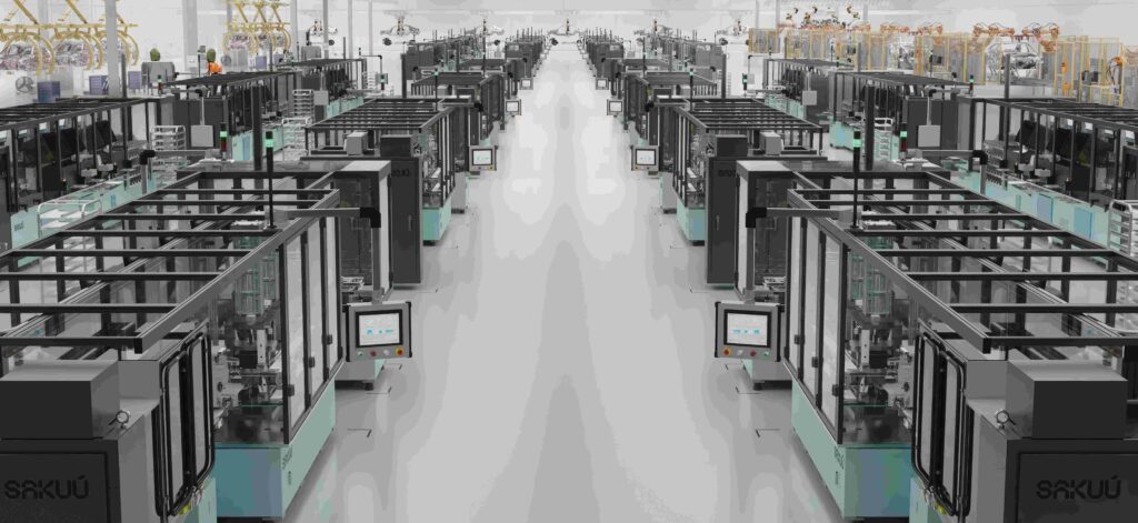
The equipment consists of a fully automated system filled with towers of channels resembling large, automated warehouses. The equipment required has a large impact on the final dimensions for the production plant due to the high volume of cells that are processed simultaneously.
Machine learning and artificial intelligence are increasingly common, using the data from the process to provide continuous improvement.
(Image courtesy of Sakuu)
Solid state
Existing lithium-ion batteries have the advantage of a liquid electrolyte, which makes it easier for ions to flow back and forth between the anode and cathode. On the other hand, all-solid-state batteries feature a solid electrolyte, which requires certain fabrication techniques and material selections to make it easier for ions to flow.
These alternative techniques include stamping to increase the density of the inside of the solid electrolyte, and performing special processing techniques and selecting specific materials to ensure excellent interfacial contact between the electrodes and the electrolyte.
Stamping is necessary to increase the degree of interfacial contact between the electrolyte and the electrodes. However, applying too much pressure may damage the microstructure of the materials, and lower battery performance and/or damage other elements of the battery.
There are still many unknowns in the field of all-solid-state battery technologies, and there is no established benchmark for the correlation between the density of electrolyte and battery performance; development that focuses on both the realistic needs of mass-production and battery performance is extremely valuable.
A conventional production process for liquid lithium-ion batteries has been amended for an all-solid-state battery production process with a roll-pressing technique. This will contribute to an increase in the density of the solid electrolyte layers and it is specific to the production of all-solid-state batteries, making continuous pressing possible.
This roll-pressing technique increases the amount of interfacial contact between the electrolyte and the electrodes, and increases overall productivity. It can also consolidate several steps to speed up the assembly processes, including the bonding of positive and negative electrodes to significantly reduce the production time per cell.
This consolidation reduces indirect costs such as power consumption and it can minimise the low dewpoint environment necessary in the dry room.
Solid-state sensing
Many solid-state battery materials are pastes, so it is not the same as an electrostatic powder coating. The sensors used already work with paste materials, such as toothpaste, all the way up to asphalt and tar, so it is even more important to use sensors early on in the process as there is even less opportunity to correct consistency and quality at the later stages. This means checks on incoming materials are vital, and the sensor data can be used to ensure consistency and quality is correct upfront.
The same sensor that is used in the liquid electrolyte process can be used for the solid-state materials with a thicker viscosity as the underlying machine-learning model adapts to the different types of materials.
While data is different for a solvent rather than a solid, being able to collect all of the data with the same sensors allows battery cell makers to use the same sensor across different production lines, whether liquid,semi-solid or solid-state, regardless of the form factor of the cell.
Acknowledgements
With thanks to Sunil Kumar and Caroline Giacomin at Rheonics, Edurne Arteta at CIC energiGUNE, Annika Völp and Dirk Leister at Thermofisher Scientific, and Kenta Umetsu at Honda Motors.
Click here to read the latest issue of E-Mobility Engineering.

Some suppliers of battery cell manufacturers
Atlas Copco
Basler
CIC energiGune
Durr
Manz
Rheonics
Sakuu
Targray
ThermoFisher Scientific
ONLINE PARTNERS


