Anode materials
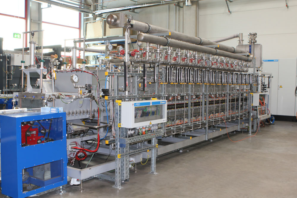
(Courtesy of OneJoon)
Charge masters
Anode materials suppliers are pouring resources into improving the performance of EV cells. Nick Flaherty reports on the latest advances
Carbon, in the form of graphite, is the mainstay of the current generation of lithium-ion batteries for e-mobility. Its theoretical maximum energy density is 372 mAh/g, but the industry is looking to increase its performance in battery anodes to boost its energy density and provide faster charging batteries with longer ranges and lifetimes for EVs. This is happening in a number of ways, using different manufacturing processes and other materials such as silicon and lithium metal.
According to the International Energy Agency, the vast majority of graphite – 85% – is mined and processed in China, although there also mines in Australia, and mines in Canada and Chile are opening to supply battery makers in North America.
Battery maker SK On has signed a joint development agreement with graphite processor Urbix in the US to establish a foothold in the US anode material supply chain. Urbix has nearly finished building a commercial-scale demonstration plant with a capacity of 1000 tons a year, and plans to expand its production capacity to 28,500 tons a year by 2025.
The company has a process that recycles 70% of the chemicals without using hydrofluoric acid and hydrogen chloride in the refining process that generates the graphite. It also uses furnaces to generate artificial graphite from the waste products of oil. OneJoon specialises in the process technology for this, working with materials suppliers on specific, proprietary recipes.
“We started with a specialised graphite material as an additive, mainly on the anode and part of the cathode, then we started to look at the market and the first project was artificial graphite as an additive and further processing as a composite material,” says Axel Weiand, vice-president of OneJoon, in Germany.
“We started to develop a pilot lab for a new process, and we are still developing synthetic graphite. Higher performance synthetic graphite will be successful but that won’t be for the mass market until there are high-performance materials with composites using silicon. It will not take a large share of the market in the next couple of years though, as there is still a strong demand for graphite; it will still be strong for the next 10 years.
“There are plenty of graphite mines in the world but the properties and energy efficiencies of the raw material from each mine differ, and with energy prices rising it is more difficult to produce artificial graphite,” he said. “Artificial carbons open up new approaches with other structures of carbon as a drop-in material.”
This approach uses an oil-based coke called petrocoke in a batch process where the coke is the electrode. Carbon black is put over the coke and high power to heat to 3000 ºC, then the graphitisation settles into layers of graphite in a grid.
“By varying the temperature we can influence the grid distance [the distance between the layers of carbon] and that is the performance criteria for the anode,” Weiand says. “Controlling the process precisely is not easy though, so it is based on a blend of materials.
“The temperature is defined by the grid you want for the graphite, so you have to run above 2200 ºC where the grid is settling, but we have to go higher for thinner layers. The energy flow to each particle is more controllable so there is more consistency from particle to particle.”
This is different from composite anodes that combine different materials with the graphite.
“Composite materials typically have a different processing route,” says Weiand. “Most are a silicon carbon composite, where you start with carbon and then synthesise to a composite or start with silicon.
“We have seen both being successful – we don’t see the real performance data of the cell later on [as that is tested by the customer] so we can’t compare the materials, but we have built equipment for both routes. Everyone is working on different ideas on how the composite can be created.
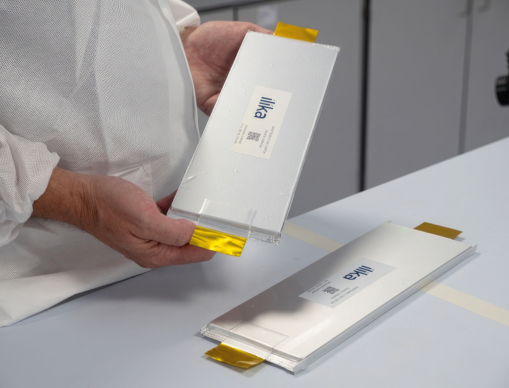
(Courtesy of Nexeon)
“We do both carbon and silicon process development, and we have our own test centre to demonstrate the structures of the material. We are not developing the process but we can take the process ideas that customers have and scale them up with testing. We can do almost any process – not just silicon but other metal based composite materials.”
Coating the anode is another issue for the process. Particles in the anode, particularly silicon, can be coated with carbon to form a composite.
“The coating can come from a liquid such as pitch that is then later run through a pyrolyser – that’s one route,” says Weiand. “But a lot of material is released from that process as gases. You can also have coating processes using carbon-carrying gases deposited on the material. The driver is not the pure efficiency of the process but the properties our customers want to achieve.”
Silicon
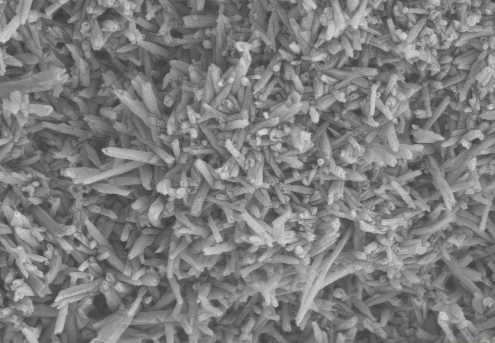
(Courtesy of Ionic MT)
Silicon is an increasingly popular material for anodes, as it has a much higher energy density than graphite, with the potential for 4200 mAh/g to create cells with a density of up to 800 Wh/litre.
However, it swells in size when it takes on the energy from the lithium ions. This swelling, which can be as much as 300%, can cause the cell to split, releasing the lithium electrolyte and potentially catching fire. It can be managed though in flexible pouch cells at the cost of the overall energy density, but causes problems with the more rigid cylindrical cell designs.
Silicon dioxide has been the initial material used for anodes but in low quantities to avoid the swelling problem.
“The appetite for silicon is there and getting stronger, and we can see that in customers testing and qualifying materials with demand forecasts, so it’s just a question of by how much and how quickly this demand will grow,” says Dr Scott Brown, CEO of Nexeon.
“The first-generation materials such as Si0x can be used with graphite up to 10% and don’t take into account the expansion; that is in production now. The second generation is engineered materials that take expansion into account by introducing porosity, and usually that’s a composite material. The third generation is the all-silicon approach with silicon nanowires on copper substrates.
“We think Gen3 requires a lot of investment in processing, it’s a slow process and it doesn’t scale. So we have focused on the first and second-generation processes, which we call NSP1 and NSP2. We have licensed NSP1 exclusively to SK Chemicals, and they are scaling up to supply the market this year and in 2024, and we have moved some of our customers over to them.
“NSP1 has advantages over a pure Si0x process, which has oxygen that reacts with lithium ions with a first cycle loss and a drop in capacity. That means having extra cathode material in the battery, which is expensive.
“Our NSP1 material has much lower oxygen levels so the initial loss is lower. We take silicon, mill it to nanoscale and spray-dry it to create a larger secondary particle in a carbon matrix. We use metallurgical-grade silicon powders, and in our case 99% purity is fine so there is a good supply chain.”
Nexeon is scaling up production for its NSP2 material. This uses silicon from silane gas deposited on a porous carbon substrate.
“The carbon is a very porous material, and the total pore volume and size and distribution of the pores are important factors and that’s what we optimise,” Dr Brown says. “The substrate is engineered activated carbon, and we deposit the silicon into the carbon pores. The final material is about 50% silicon and 50% carbon, so the capacity is around 2000 Ah/kg, as we need to leave enough space for the silicon to expand into.”
This approach avoid problems with the lithium ions plating the silicon. In tests it supports safe charging to 80% capacity in 15 minutes.
“Perfect porosity would mean there is 0% swelling at the particle level rather than 300%, but we are at less than half the theoretical limit and we have customers using that level of NSP2 without any problems,” says Dr Brown.
The availability of silane, which is also used for silicon nanotube processes, is a potential issue as production scales up. “Most of the silane currently produced goes into solar cells, but its producers see an opportunity to expand and diversify, and we are in talks about supply,” says Dr Brown.
The process also takes place at a lower temperature than that for graphite, which is key given the high cost of energy. “We don’t use vacuum and we do not go above 500 ºC so it’s a relatively straightforward process and its scales very well from a process time perspective,” says Dr Brown.
“In principle it can be a continuous process, which is more efficient, but there is middle ground. A batch process can be semi-continuous with short batch times and minimal loading and unloading times with cooling/heating, so you can call it semi-continuous.”
Another key feature of the process is that the waste product is hydrogen, which can be used for its thermal properties, be used in clean technology applications or returned to the silane producer.
Silicon nanotubes

(Courtesy of Paraclete Energy)
Rather than using silane to produce silicon nanoparticles, Ionic MT has taken a very different approach, and is also able to mine the particles directly.
“We have a very different and more scalable way to mass-produce nanosilicon,” says Andre Zeitoun, CEO and founder of Ionic MT.
The company has a mine in Utah, in the US, that produces aluminium silicate with a range of silicon nanotubes of different sizes. It has developed a process for etching out the aluminium using sulphuric acid and then filter and re-precipitate the silicon as a high-purity element.
This produces particles that are 50 nm in diameter and 0.5 µm long, and they are used as the feedstock to produce nanotubes that are less than 150 nm long. The patented process is a metallothermic reduction that uses different types of magnesium in an unsealed reactor, along with mainstream industrial equipment for continuous operation.
The feedstock is blended with magnesium metal, heated to 650 ºC and then the magnesium acts as the scavenger of the silicon oxide and leaves silicon metal nanotubes. The magnesium is then removed as hydroxide.
This is more scalable than silane chemical vapour deposition process and does not need an etching process using hydrogen fluoride at the end.
“Right now we are seeing 30% substitution of silicon as a drop-in material in graphite anodes, so that gives 1100 mA/g and the target is 1200 mAh/g for blended anodes,” Zeitoun says.
“The issue is the cell expansion during charging, so 150 nm is the upper limit for the size of the smallest silicon particles to ensure they don’t crack open and form an inhibiting layer, the solid electrolyte interphase [SEI] later. That’s why silicon is limited to 10% in graphite anodes at the moment.”
This can produce pure silicon anodes with an energy density of 3000 mA/g compared with the typical 350 mA/g of graphite, but there are issues with the electrolytes. “You can have 100% pure silicon, but as soon as you put that into a water-based binder – which is where the market is going – it will surface passivate with a thin oxide coating, and that is a problem,” Zeitoun says.
“The trick is finding the right balance. For example, a 75% silicon anode performs better than one with 99% silicon.”
The company has only explored 30 acres of the 650 acre mining site, and the silicon is accessible with surface mining across 160 acres, avoiding the higher costs of deep mining. It has developed anode materials and built battery cells in-house and is testing them with graphite blends to 1100 mA/g and silicon anodes up to 3000 mA/g.
Polymer matrix
Paraclete Energy has also developed a process for making silicon anodes using a polymer matrix rather than graphite.
This is a replacement for SiOx materials that can be dropped into existing battery anode processes and offers a theoretical maximum capacity of 1500 mAh/g. This addresses the issue that adding more than 10% silicon to existing anodes actually reduces a cells energy density and stability.
“We use a polymer matrix – we can use any source of silicon, whether mined or solar-grade,” says Jeff Norris, founder and CEO of Paraclete. The process starts with 150 nm-diameter silicon particles in a polymer sphere with a diameter of 5-7 µm.
“We put a polymer matrix around the silicon, which gives it elasticity with self-healing. The architecture handles swelling in the polymer and stops the electrolyte getting in,” he says.
“We allow the silicon to expand as we put an artificial SEI around the silicon to create a primary particle. Then we place that in a non-silicon shell which is ionic and conductive on top of the polymer matrix so that the electrolyte forms the SEI on the shell.”
This approach is being used for anodes with 25% silicon to give existing battery packs a range of up to 1000 km, Norris says.
“Our customers are routinely achieving 1000 charging cycles because of the polymer and the electrolyte is not consumed,” he adds, “We started testing with customers in late 2021 some of who are in their third or fourth cycle of optimisation for performance.
“Each cathode has a different voltage and range, and traditionally you need to match that with the graphite and the silicon. That’s not necessary with our silicon, as we’ve taken out the carbonisation stage so we don’t need the massive manufacturing infrastructure.”
Using a polymer is a low-temperature (sub-500 ºC) low-waste process that can be installed at the battery cell manufacturing plant or even the EV plant. “97% of the chemicals used in the process are recaptured and 3% are used on the product,” Norris says. “We don’t use carcinogens, we use commodity chemicals and equipment, and because we are using surface modification, all the materials are stable in air and we only have 2% swelling as we have no oxides on the surface.”
The low temperature is not an issue for the cell manufacturing process. “We have no problem up to 400-500 ºC for the battery, and above that there are high-temperature polymers we can use,” he says.
The polymer can also be changed to work with the sulphide electrolytes being used in solid-state batteries. “We change the chemistry to be compatible with the solid electrolyte, so it could be sulphide-based. We can add a reactive group to have an affinity with the chemistry of the electrolyte in the polymer.”
The process is currently in qualification with battery cell makers, with production later this year and in 2024.
Lithium metal anodes
(Courtesy of Li-Metal)
Using lithium as the anode has even higher theoretical energy density than silicon, but there are major challenges.
One is a gap in the supply chain for next-generation batteries for high-performance anode materials, says Maciej Jastrzebski, co-founder and CEO of Li-Metal.
“On the one hand the technology is starting to get to the point of being taken seriously with testing for EVs, but on the other there is a gap in metal production and understanding the drawbacks, and coupling that with a production process for low-cost anodes,” he says.
Between 7000 and 20,000 tonnes of battery-grade metal will be needed by 2030; the industry currently has a capacity of 7000 tonnes of nominal capacity, with half of that used for batteries. The lithium is produced from lithium chloride via lithium carbonate from brine, or lithium sulphate from rocks, but the latter needs to be refined to lithium carbonate and then turned back into the chloride.
“This creates an upstream problem, so the challenge is to turn the carbonate feedstock into metal,” Jastrzebski says. “We are looking at taking lithium carbonate and turn into LiCl as a precursor.”
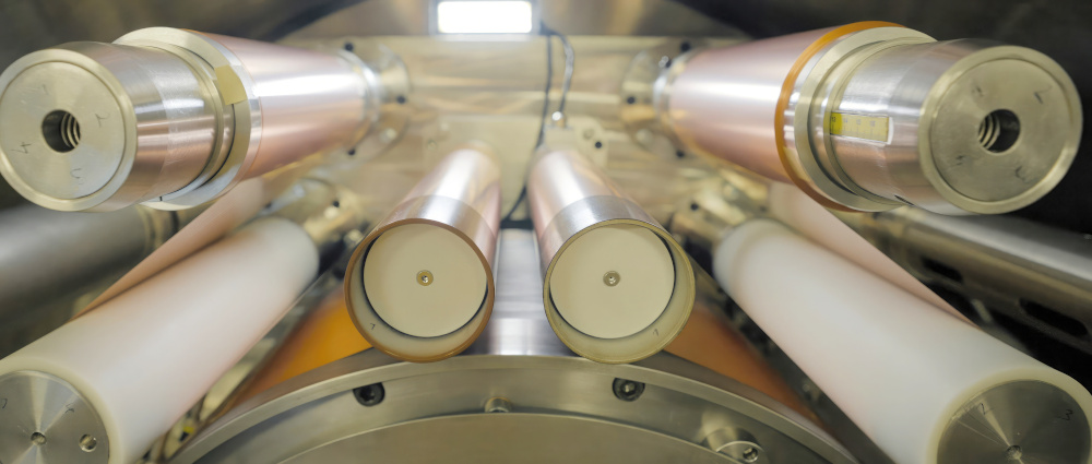
Current production use a rolling process, extruding the lithium into a foil 200-300 microns thick. However, there is a problem in that keeping the foil from breaking or splitting becomes harder as the foil gets thinner, and is harder still as the lithium metal itself is weak.
“You can cut it with a knife, so the problem of rolling the material is profound,” Jastrzebski says. “It ends up much thicker than you want it to be, and you are forced to build the cells using thin strips of lithium.”
One of the challenges is the need to minimise the inclusions in the metal, as they create splits in the foil. “This forces people into strange-size formats, and I see rolling as a dead-end technology,” he says. “You are composing the anode to make the rolling as easy as possible, which constrains the anode’s performance.”
Li-Metal has therefore developed a process using vacuum-based physical vapour deposition (PVD) similar to that used for the thin metallic coatings on bags of potato crisps.
“What attracted us to this approach is the economics and commercial availability of the equipment as a manufacturing platform,” Jastrzebski says. “The other, less appreciated characteristic is that the cost of PVD versus foil rolling falls for thinner materials which is exactly what you want.
“The costly part is the vacuum. Getting the material into a vacuum is the initial cost, but the cost of adding other materials is very low. You can modify the composition of the lithium with various alloys to suppress dendrite formation and create layered structures with a protective layer on the surface. Because you are laying the materials on a substrate you are no longer bound by the mechanical strength of the lithium, and the substrate becomes the current collector.”
“The metallised films can be up to 2.5m wide, and we have a substrate 200 mm wide that allows us to verify the process. In theory, to broaden that substrate is not too difficult, as it is a known process.”
The process starts with a copper foil 6 µm thick, with varying thicknesses of lithium up to 25 µm thick deposited on top, although a thinner layer provides a lighter anode without reducing the performance. That reduces the cost, and speeds up the process compared with rolling,
“You end up with 40-60% of the cost being the metal cost, 20-30% the depreciated machine cost, and the rest as the processing cost,” Jastrzebski says.
PVD can also be used to add other layers to the anode, such as protective coatings or changing the structure of the lithium in the anode to suppress dendrite formation. The technique can also be used for solid-state batteries.
Solid electrolytes have a higher affinity to the lithium but with polymer electrolytes there’s lower ion mobility so the cell cannot charge as fast. Oxides and sulphides have similar conductivity but are either difficult to process, allow dendrites to form or end up with a heavier cell as the materials are very dense.
“We are looking to deposit high-performance materials using a low-cost process. It’s definitely possible to deposit complex ceramics on surfaces using PVD,” Jastrzebski says. “PVD allows the structure and chemistry of the anode to be modified in many ways, contingent on producing the material fast enough to offset the capital cost of the equipment.
“We are shipping these materials to battery developers now. Most are looking at pouch cells, but we produce rolls of materials by design, which works well with mass production, and we are working with partners on a demo facility for the qualification of samples.”
3D printing

(Courtesy of Sakuu)
Battery start-up Sakuu has demonstrated a lithium metal battery cell with an energy density of 800 Wh/litre, and believes it can achieve 1200 Wh/litre. It uses a proprietary electrolyte that is non-flammable .
These batteries were printed as cells containing patterned openings for thermal management, in a fully dry process, at Sakuu’s Silicon Valley battery pilot line.
This is a key step for the planned commercial-scale production of next-generation batteries which Sakuu calls SwiftPrint, including a solid-state version. These will be printed on the company’s Kavian 3D-printing platform.
“Our development shows that the Kavian platform can enable commercial-scale, sustainable production of a wide range of battery technologies, from lithium-ion to lithium metal and even solid-state batteries,” says Karl Littau, CTO at Sakuu.
Sakuu uses a multi-material, multi-layer approach with a dry process instead of layer-on-layer printing or screen-printing. The first printed batteries have demonstrated successful cycling performance at C5 rates with energy densities from 800 to 1000 Wh/litre.
The patterned approach allows the integration of sensors and thermal transport pathways, as well as regulation through the patterned design, especially when thin sub-cell battery structures are stacked with identical patterned openings for thermal management in alignment.
Conclusion
Making battery anodes can be an energy-intensive process with lots of nasty chemicals. The ability to drop a material into the existing process of making an anode to boost the energy density is attractive. The current silicon oxide materials allow that, with modifications to sidestep the initial drop in capacity that comes as a result.
New ways of producing composite particles without the high temperatures and corrosive chemicals are gaining traction and enabling a new class of anode materials with far higher energy densities and more cost-effective production.
In addition, existing PVD and 3D-printing technologies are improving the process of making high-capacity anodes without high temperatures or caustic materials.
ONLINE PARTNERS


