Motor laminations
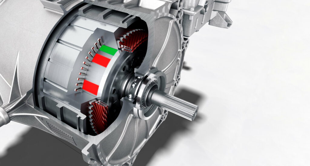
(Courtesy of Porsche)
Layer by layer
Peter Donaldson reports on how lamination technology has evolved in recent times to meet changing demands from the EV industry
Whether or not governments eventually ban the manufacture of fossil fuel-powered vehicles, it is clear that the electrification of transport fleets is set to accelerate and that the EV industry will therefore need traction motors in massive numbers with consistent quality at low cost. This pressure affects every component of these electrical machines, not least the laminations that form the rotor and stator cores.
Along with low-resistance copper windings and powerful permanent magnets, rotor and stator cores shape the performance and efficiency of rotating electrical machines, and they must be built from thin layers of highly conductive material, principally steel alloys. Such laminations are the means of minimising loss-generating, heat-emitting eddy currents generated in them by electromagnetic interaction with the currents passing through the windings.
One electrical steel producer we consulted in connection with this article notes that the market for traction motors and consequently for motor laminations is one of the fastest growing parts of the automotive industry. They describe the sector as being very dynamic, with fast-changing requirements for motor characteristics driving continuous development of technologies and materials.
Also, a lamination tooling specialist describes the growth in the sector as exponential. It adds that many corporations in the automotive industry that for decades have supplied parts for IC-engined vehicles have seen the writing on the wall and are trying to make inroads into the EV sector, many of them by developing their own drive units.
With so many new players in the market, the specialist says, lamination designs have evolved significantly over the past decade. A new generation of motor designers have extended the envelope for lamination geometries, and many old rule-of-thumb constraints have been pushed to the limit.
Minimising losses
Eddy currents are closed loops of electric current induced in conductors by changes in magnetic fields, circulating in planes perpendicular to the magnetic fields. According to Lenz’s law, eddy currents create their own magnetic fields that oppose changes in the initial magnetic fields that created them.
That reduces the efficiency of electrical machines. Not only is the machine effectively fighting itself, the currents also generate heat, which represents lost energy as it has to be removed to keep the motor at a safe operating temperature.
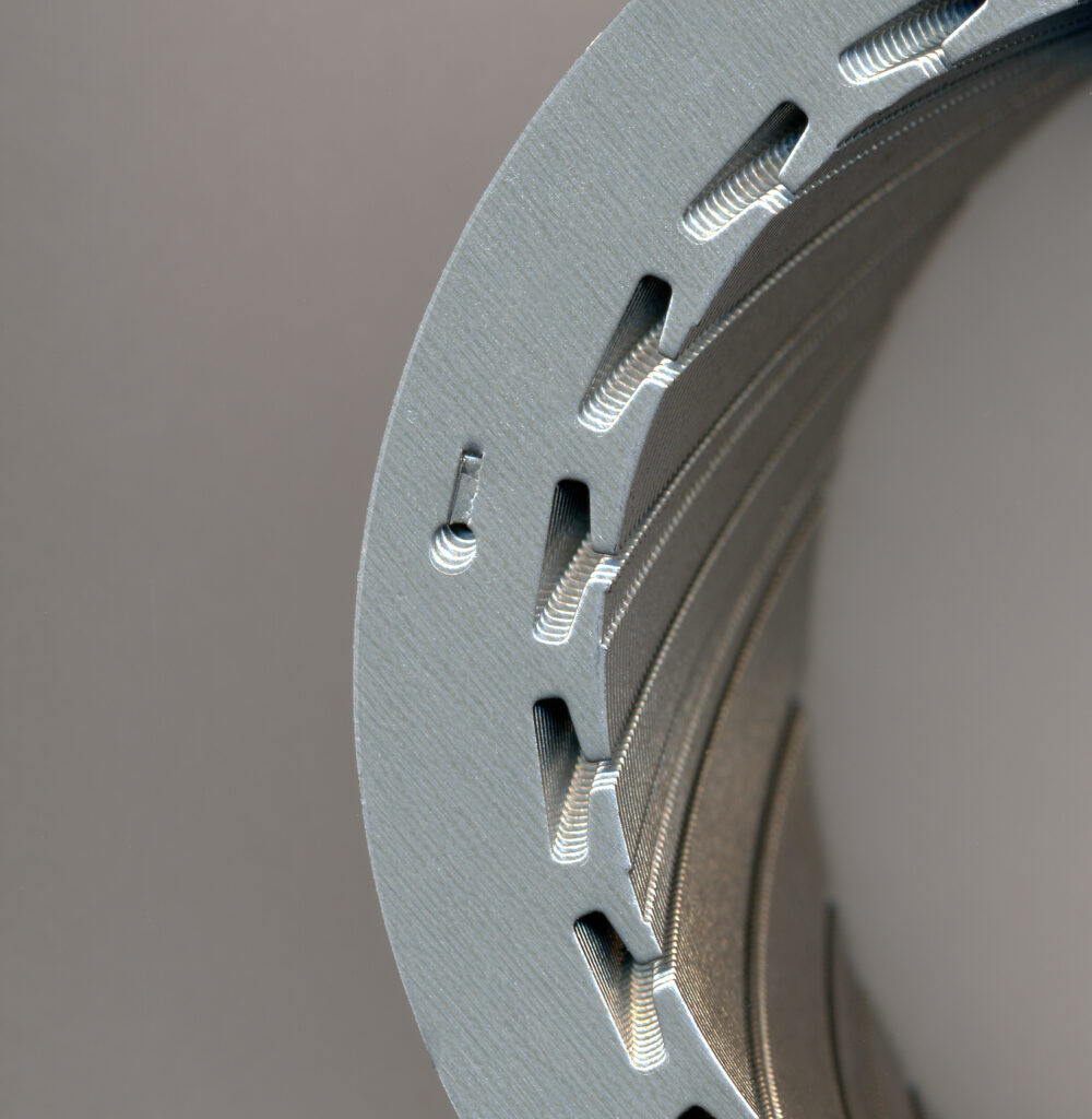
(Courtesy of Tata Steel Europe)
The standard way of minimising the problem is by constructing rotors and stators from layers of steel that are as thin as is practical, oriented to lie as parallel as possible with the lines of magnetic flux and separated by insulating layers. Thin layers limit the size of the current loops that can form and, because current is proportional to the area of the loop, minimising the area also minimises the amount of current that can flow. Because the power dissipated by an eddy-current loop is proportional to the square of the current, small reductions in current bring much larger reductions in losses.
Reaping benefits that are disproportionately greater than the magnitude of the reductions in laminate thickness is what drives the industry’s efforts to produce rotor and stator cores built from ever-thinner layers. That’s far from the whole story, however, as the magnetic and electrical properties of the materials are also critical.
While laminations for industrial motors are typically made from steel between 0.35 and 0.5 mm thick, the trend in traction motors is to use much thinner gauges to drive down eddy-current losses – 0.2 mm is now considered practical for volume manufacturing, and still thinner layers are under development.
Making a good electrical machine also requires balancing the demands in the electromagnetic, structural and thermal domains, a producer of high-performance speciality alloys points out. Which materials are best though depends heavily on the application.
In most high-volume EV applications, motor laminations are made from silicon steel, says the alloys company. However, in EVs higher up the performance scale and in heavy-duty commercial vehicles, where the application requires greater torque and power density, high-induction and low-loss iron cobalt alloys come to the fore.

Steel requirements
Although the imperative to increase motor/generator performance while reducing size, weight and cost is a constant – and many different e-machine concepts are developed to meet that in their intended applications – the steels used in their rotors and stators must always fulfil the same set of requirements, the electrical steel producer says.
These include supporting high magnetic flux, which depends on a high saturation level and good permeability. The material must also support rapid changes in the magnitude and direction of the magnetic field, for which materials with low coercivity tend to be preferred because they enable higher torque densities and lower losses.
Higher electrical resistivity is also preferred because it limits the circulation of eddy currents and reduces the associated losses, particularly in high-speed applications. If the resistivity of the laminate stack as a whole is not the same in all directions (anisotropic) then steel with higher resistivity in one direction is also desirable, says the alloys producer.
Thermally speaking, higher conductivity is usually an advantage. Most, if not all, motor components prefer to run cool, and overheating is a major constraint in motor design. Higher thermal conductivity in the laminations therefore speeds the transfer of heat from source to sink, and increases the motor’s power density. This property is subject to a trade-off though, in this case with resistivity, as it is not easy to optimise them both without compromising other properties.
With these general requirements in mind, engineers looking for the best materials for their designs seek the right balance between thin, high-alloyed materials that minimise power losses for high-frequency applications, high permeability that enables higher torque outputs, and high yield strengths. Insulating coatings and the way laminates are joined together are also important.
Managing interdependencies

Striking the right balance is challenging, a second steel specialist we consulted points out, because these properties are not independent. For example, a higher percentage of alloying elements reduces power losses, which is an advantage, but it also decreases permeability, which is a disadvantage.
This fundamental interdependence of key parameters is the root of the complexity in e-motor design, which means it is not possible to define a standard set of simple rules for creating laminations for different types of motor/generator.
What’s more, lamination design is heavily influenced by the type of motor for which they are intended, which can include DC and AC, synchronous and asynchronous, permanent magnet and induction, radial flux, axial flux and transverse flux machines. The geometry of their laminations is becoming increasingly complex in the drive to achieve ideal performance-to-volume-ratios and to incorporate features such as cooling passages, a provider of metal-forming tools and systems notes.
The choice of material is also becoming more critical. In general, this depends more on the application and operating region than the motor type, which has a more indirect influence because in any type of motor the operating frequency and induction level can be either low or high, according to the speciality alloys provider.
That said, all the types of electrical machine referred to above have their own sensitivities to key parameters such as magnetic permeability and coercivity, electrical resistivity and thermal conductivity and so on, adding to the complexity of the issue. These differences do however allow some material selection heuristics to emerge, the stack producer notes.
Materials and motor types
For permanent magnet synchronous machines, eddy-current losses (Watt losses) are particularly important; thin layers are needed to minimise them, along with the mechanical strength to secure magnets in rotors at high rotational speeds. Because asynchronous machines are not so sensitive to such losses, thicker material is used and laminations might typically measure 0.35 mm.
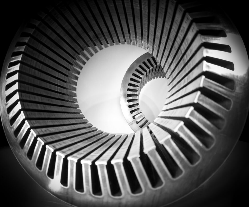
Axial flux and transverse flux machines have different flux paths from those in more widely used radial flux machines, and sometimes the flux moves in three dimensions. In this case, the use of soft magnetic composite or other 3D flux materials is key, the alloys provider says.
(Courtesy of Carpenter Electrification)
Induction machines require high magnetic permeability, the stack producer notes, and one important condition that the motor designer must make is whether to use the same or different materials – one optimised for the rotor, the other for the stator laminations. Using different materials can result in a lot of scrap during manufacturing, particularly with the stator, for which segmented assembly is a popular solution.
The alternative of using the same material for both rotor and stator laminations requires a steel optimised for strength and with good – but less than ideal – magnetic properties. The rotor would be assembled from components made from this material without further property-changing treatment, says our second steel producer, while the stator laminations would be annealed at the customer’s facility to optimise their magnetic properties.
Annealing is a heat-treatment process in which the steel is brought up to a specific temperature, held at that temperature to ‘soak’ and then cooled at a controlled rate. As well as enhancing the metal’s electrical and magnetic properties, annealing also softens it to make it easier to work when cold and improves its machinability.
As well as the fundamental characteristics of the materials, engineers must also take economic and strategic factors into account when making their selections, the stack maker adds. These include the number of steel mills that can produce the steel to the right specification: the specifications are quite demanding, so the choice of available grades tends to be limited, and changing suppliers during a project is difficult.
Processability must also be considered because, for example, the thinner the material the more laminations are required for a given stack height. All these factors lead to longer processing times and the need for more machines to stamp out the layers.
With cost, power density and efficiency over a wide speed range in mind, says the speciality alloys producer, thin-gauge silicon-iron laminate seems to offer a good trade-off between cost and performance for now, with cobalt-iron materials becoming an interesting option for future high-performance applications.
Demanding power and torque densities
Motors and generators with very high power and torque densities are particularly demanding on laminations.
A key reason for this is that this performance is typically designed into compact electrical machines that run at ever-higher rpm, resulting in higher internal switching frequencies along with larger mechanical stresses and stress fluctuations in the rotor, our electrical steel producer notes. The higher frequencies lead to larger losses that must be compensated for with better magnetic properties in the steel, while the higher mechanical stresses can lead to plastic deformation and/or fatigue, requiring stronger materials to resist these forces.
Laminations for motors designed for high torque and power densities are typically made from electrical steels with high permeability. To achieve high permeability, the alloying content of the steel must be limited, and that can make it more challenging to keep power losses to a minimum.
However, such losses can be kept down even in steels with lower alloy content by reducing lamination thickness, although high strengths are not possible, according to the stack manufacturer. The company also points out that the processability in terms of stamping behaviour of low-alloyed and high-alloyed materials are different.
This is significant, because one potential means of increasing these parameters in EV traction motors is by using soft magnetic materials, such as the aforementioned iron cobalt, that exhibit high induction and low loss characteristics, according to the alloys provider.
Over the past decade, the lamination tooling expert says, the pursuit of greater efficiencies and higher rotational speeds has seen much higher demand for advanced means of ensuring the structural integrity of laminate stacks through the use of bonding varnish (also known as backlack) and glue-dot bonding, with implications for thermal management.
Managing heat flows
Heat in motors and generators comes mainly from the losses in the electrical steel in the rotor and stator, although the copper losses from resistance in the windings is also important.
Although using steel with low electrical losses reduces waste heat at source, the alloying elements used to achieve this are principally silicon and aluminium that unfortunately reduce the steel’s thermal conductivity. In most cases, the steel supplier points out, low losses are given a higher priority than thermal conductivity, so waste heat has to be managed by other means.
(Courtesy of Voestalpine Automotive Components Nagold)
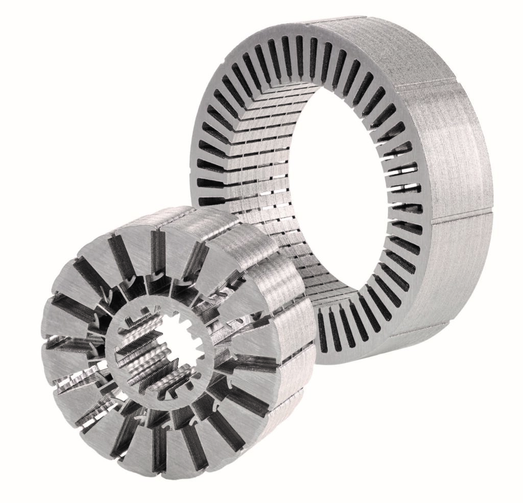
However, the thermal conductivity of the stack as a whole can be increased by full-face bonding of the laminations using backlack, because the varnish (which is also an electrical insulator) has a higher thermal conductivity than the air left in the gaps between individual laminations that don’t have full-face bonding.
Laminations themselves have evolved significantly over the past decade, with thinner grades becoming available and losses for a given thickness reduced, particularly at higher frequencies, the electrical steel supplier says. It adds that new steels that exhibit better combinations of mechanical strength magnetic losses have also been developed.
In laminate manufacturing, the biggest development over that period relates to the strip thickness it is possible to use in high-volume production, the supplier adds. Around 10 years ago, the limit was generally considered to be about 0.3 mm, but these days many projects are looking at 0.2 mm and are aiming to start production in the near future.
In current new projects, the stack manufacturer notes, laminate thicknesses of between 0.25 and 0.3 mm are already being used in stators, with up to 0.35 mm for rotor applications because of the need to resist rotational forces. Demand for higher strengths, meanwhile, is being driven by engineers’ decisions to use the same material for both stator and rotor for the reasons outlined above.
For niche applications, however, even thinner grades of electrical steel are already in use, with some specialised and highly efficient motors containing laminations as fine as 0.1 mm, the electrical steel supplier says.
Inevitably, industry looks for ways to expand the application of technologies initially suited only to narrow niches. To that end, the alloys provider says it has optimised the cost and performance of 0.1 mm laminations for mass production, pushing the practical processing limit for niche applications down to half that figure.
Drawbacks to slimming
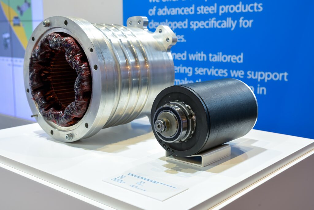
In principal, the thinner the laminations the better, because of their beneficial effect on eddy-current losses at higher switching and commutating frequencies, and consequently, on efficiency, but there are practical drawbacks, the electrical steel supplier adds. Thinner laminations are more difficult to stamp and assemble into stacks, which can cause quality problems and increase costs.
(Courtesy of Tata Steel Europe)
The stack manufacturer points out that thin laminations are not necessarily better for permeability, as this desirable property is independent of thickness. What’s more, thin laminations don’t improve the stacking factor either.
The stacking factor is the ratio between the actual mass of the stack, consisting of all the laminations and any material between them, and its theoretical mass if it were made of solid steel, which would be the ideal situation for amplifying the magnetic fields generated by the copper coils if it were not for the eddy-current issue. Very thin laminations mean that more of the stack’s volume is taken up by the bonding/insulating varnish between them.
Practical limitations affect how thin the laminations can be made, however. In addition to the stacking factor described above, these include the effect on the capacity of existing production lines, which reduces with the thickness of the material they are set up to process and the relatively small number of mills that are equipped to turn out such thin product, the second steel maker says.
Furthermore, the thinnest grades are more difficult to process into stacks. For example, interlocking each layer with its neighbours is considered impossible at thicknesses of less than 0.25 mm, while many more laminations are needed for a given stack height, so more strokes are needed on the stamping line, and the thinner the material the more gently and carefully it must be handled, the company cautions.
This highlights the trade-off facing motor designers between the benefits of lower losses that flow from thinner laminations. The speciality alloys provider emphasises that a motor/generator made with thinner laminations takes longer to manufacture and costs more than one built up from thicker ones.
Stack-joining techniques are often chosen on the basis of the robustness required of the finished stack, which can differ between motor components – for example, stators are not subject to the same forces as rotors, the alloys company points out. The most appropriate joining technique can also be affected by the required production volume, with different methods typically used in mass production and prototyping.
Manufacturing advances
Lamination manufacturing technology has moved on, pushed by the demand for compactness in stacks along with reduced noise and vibration. Also, the geometrical accuracy of the stacks is increasingly important, emphasises the stacks manufacturer, which puts pressure on steel suppliers to provide material with highly consistent mechanical properties to meet the specifications.
Different stacking methodologies have also been developed to maintain the electrical insulation between the laminations, with an emphasis on cost-effectiveness for volume production.
Laminations for traction motors built in high volumes, for example, are typically cut and shaped from the sheet metal in stamping machines equipped with progressive die sets in which the material passes from one stage to the next, each stage performing a simple cutting or bending operation to produce the finished component. Thinner gauges and more complex lamination designs require more stages in the die sets, says the metal forming systems specialist, which therefore have to be longer and need larger presses to accommodate them.
The company has extended the press bed of its latest machines dedicated to EV motor production, providing space for it to clamp the longer progressive dies needed for increasingly complex lamination geometries. These machines also feature a control mechanism developed in-house specifically to check the depth of die penetration at each stroke and adjust it in fractions of a second to ensure accuracy in formation of the parts from the first stroke.
To form the rotor or stator core, the resulting laminations can be loosely stacked, interlocked, welded or bonded with adhesives, or some combination of them, the electrical steel maker says, with cost and the required stack tolerances being the most important factors influencing the choice among them.
Interlocking in the press, often supplemented by welding, is the most commonly used method, because it provides a good combination of tolerances and cost. With interlocking progressive tooling, small portions of each single lamination are pressed down into the one underneath it in the die. Known as clinching, this forms tiny depressions called dots that keep the stack together.
Interlocking is a highly productive and well-proven technology, the metal forming systems provider emphasises. It offers high output, easy stack handling and a wide choice of suppliers of production equipment such as tools and dies. However, one increasingly important disadvantage is that the clinching dots create shortcuts between the layers that are detrimental to the motors’ magnetic properties.
Using very thin layers of steel though makes it difficult to form these clinching dots, resulting in small joining forces, low stack density and sometimes unsecured stacks. For this reason, interlocking is reaching its limits as far as stamping advanced traction motor cores is concerned, with laminates 0.2 mm thick already proving a challenge for the technique.
Gluing involves applying an adhesive in the stamping tool before the rotor and stator parts are cut out, then pressing the layers together with the glue in between. In this way, the electrical isolation coating on the steel remains undamaged, which is not the case with interlocking.
This is an attractive alternative to interlocking, because both interlocking and welding increase eddy-current losses in the stack, so there are opportunities to increase quality by using advanced bonding techniques, says the electrical steel maker.
Two main adhesive bonding technologies are used: dotted gluing and full-face bonding. Because (as the term suggests) dotted gluing only fixes each lamination to its neighbours in the locations where the dots are, it is not as strong or as stable a method as full-face bonding, which can produce stacks that exhibit very fine tolerances and high mechanical stability.
Backlack and full-face bonding
At this point it is worth examining full-face bonding using backlack in more detail. The process is said to contribute substantially to the behaviour of the steel inside an electrical machine, and is described as the least damaging and most flexible means of joining laminations to form a coherent stack. Well-suited to the use of very thin steel, it also allows for more intricate shapes in the laminates, the metal forming specialist says.
After the laminations have been punched out of backlack-coated sheet steel feedstock, they are thermally bonded in two steps. In the first step, the applied heat softens the varnish and then melts it after completion of a chemical reaction that imparts high bonding strength along with high resistance to various media.
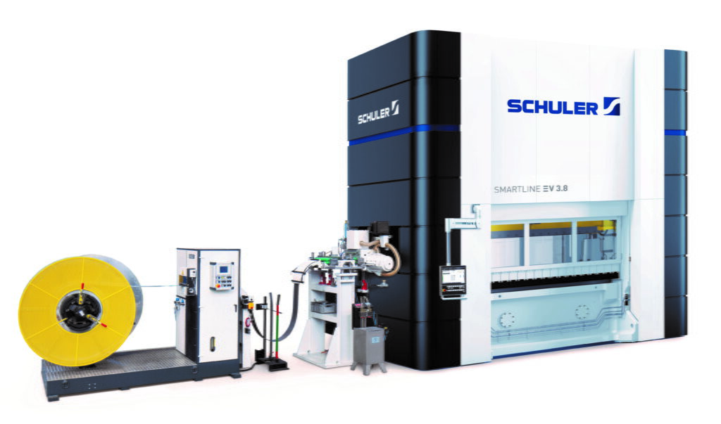
(Courtesy of Schuler Group)
In the second stage, a further increase in temperature hardens the self-bonding varnish and transforms it into a stable, highly crosslinked, high-viscosity polymer. This material holds the laminations together and fills the gaps between them.
The technique provides a great deal of design freedom, allowing for the thinnest webs and tightest tolerances without having to consider bonding points such as welding seams and clamps. Without imperfections such as welding seams, for example, which could change the properties of the base material, the steel also retains its desirable magnetic properties.
Another benefit is mechanical stability, as the process prevents the laminations from fanning out and produces a compact stack that can be easily milled to accept the magnets. There are also acoustic advantages, the stack manufacturer notes, as the varnish between the layers of steel has a strong damping effect that reduces noise and vibration.
With additive manufacturing (AM) techniques such as 3D printing making inroads into many areas of industry, it is natural to look at electrical machine laminations in the light of the technology. So far, its impact has been very small because it faces a fundamental difficulty when it comes to reducing eddy current losses in the final rotor or stator, and production of rotors and stators as single pieces by AM would lead to poor magnetic behaviour. Theoretically, laminations could be produced, but only as proof-of-concept or prototype parts, says the stack manufacturer. Their chemical composition would be acceptable, but grain size and texture would differ from those of good standard material.
Soft magnetic composites consisting of ferromagnetic powders, the particles of which are surrounded by an insulating film, can be built up into complex 3D shapes in AM machines, and they have found uses in electromagnetic systems.
However, the permeability and strength of the cores in which they are used is relatively poor and have so far limited the applicability of these materials. While they have the potential to reduce losses and improve power density, the technology has some way to go before it is mature enough to demonstrate parts with the right mechanical and magnetic properties, along with the scalability for volume production.
As an aside, the use of AM could lead to improvements in the design of the dies used to stamp out the laminations, because stamping is so much quicker and more efficient.
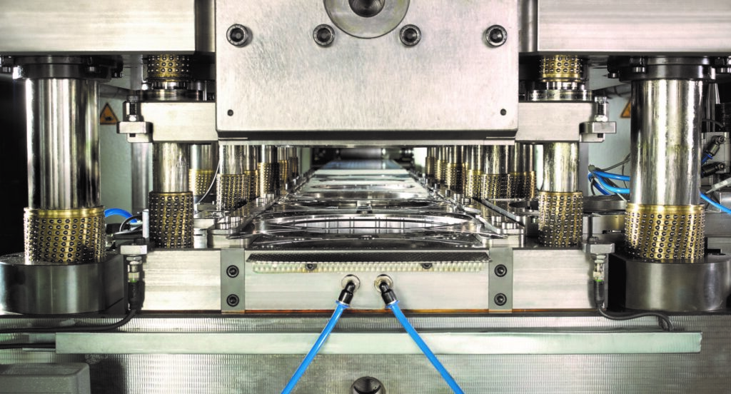
(Courtesy of Voestalpine Automotive Components Nagold)
Future directions
The trend towards thinner laminations with lower losses and greater strength is expected to continue, says the electrical steel maker, adding that bonding technologies will evolve. If they prove low enough in cost and fast enough in manufacture, they could replace interlocking and perhaps even welding as a means of holding laminated stacks together. The use of backlack in particular is expected to grow.
Lamination thicknesses down to 0.25 mm are expected to be routinely used in large commercial production runs, according to the stack manufacturer, while stress-relief annealing is likely to see more widespread use to remove the influence of the stamping process on magnetic properties.
Motor designers are expected to continue introducing more complex features into lamination stacks in the effort to optimise cooling as well as magnetic performance and overall efficiency, the speciality alloys provider says, who also anticipates that further progress in automation and process optimisation will lead to consistent and tighter geometric tolerances. Further, with enhanced testing finding disparities between magnetic samples and the final stack, it provides an opportunity to target the specific problems revealed.
Traction motors are expected to benefit from improvements in the way backlack is used, with a focus on greater automation to deal with the problems arising from the need to handle loose laminations, for example, better suiting it to mass production.
The metal forming specialist has developed a fully automated system that collects freshly stamped steel layers from underneath the progressive die set and transfers them to free-standing bonding units. These units are designed to allow full control of process parameters such as pressure, temperature and time, and are offered as a turnkey end-to-end system encompassing all the processes, from de-coiling of the raw material to the completing the stack.
The company proposes a system combining a high-speed press and bonding stations capable of turning out more than 500,000 bonded rotor stack a year, with the flexibility to adapt to different part sizes, volumes and ramp-up rates, and with digital solutions for traceability, data archives and process improvement applications.
This kind of approach is likely to be essential to generate the production volumes required to electrify global transport on the timescales currently envisaged.
Acknowledgements
The author would like to thank Patrick Walker, Jaydip Das and Mingda Liu at Carpenter Electrification, Barry Lee at LH Carbide, Markus Roever at Schuler Group, Basjan Berkhout at Tata Steel Europe, and Roman Sonnleitner at Voestalpine Steel Division for their help with researching this article.
Some suppliers of motor lamination services
Austria
Andritz Kaiser +49 7252 91001 www.andritz.com
AndritzVoestalpine +43 50304 15 0 www.voestalpine.com
Germany
Schuler Group +49 7161 660 www.schulergroup.com
Tata Steel Europe +49 211 4926 0 www.tatasteeleurope.com
Vacuumschmelze +49 6181 38 0 www.vacuumschmelze.com/
Italy
Aussafer Due +39 0431 66501 www.aussafer.it
Dema +39 019 9354711 www.demasassi.it
Euro Group +39 02 35 0001 www.euro-group.it
Switzerland
Feintool +41 32 387 5111 www.feintool.com
UK
Brandauer +44 121 359 2822 www.brandauer.co.uk
HV Wooding +44 1303 264471 www.hvwooding.co.uk
USA
Arnold Magnetic Technologies +1 585 385 9010 www.arnoldmagnetics.com
Carpenter Technology +1 610 208 2000 www.carpentertechnology.com
LH Carbide +1 260 432 5563 www.lhindustries.com
Oberg Industries +1 724 295 2121 www.oberg.com
Tempel +1 773 250 8000 www.tempel.com
ONLINE PARTNERS


