


")


")


V2H & V2G bidirectional charging

(Image courtesy of Hyundai)
Every which way
Nick Flaherty reports on the latest innovations in bidirectional charging and their ageing effects on battery cells
Bidirectional charging allows energy to flow back and forth between an e-mobility platform such as an EV and other systems, whether that is the electricity grid, other electric equipment or even other vehicles.
However, the technology relies on specific chargers in the vehicle and the home. Recent vehicles are being equipped with bidirectional onboard chargers (OBCs), making use of the latest power devices with silicon carbide (SiC) and gallium nitride (GaN).
The latest chargers are also adding bidirectional charging and standard CCS connectors, enabling new uses such as virtual power stations, but there are potential issues with the ageing of the cells in battery packs that needs more research.
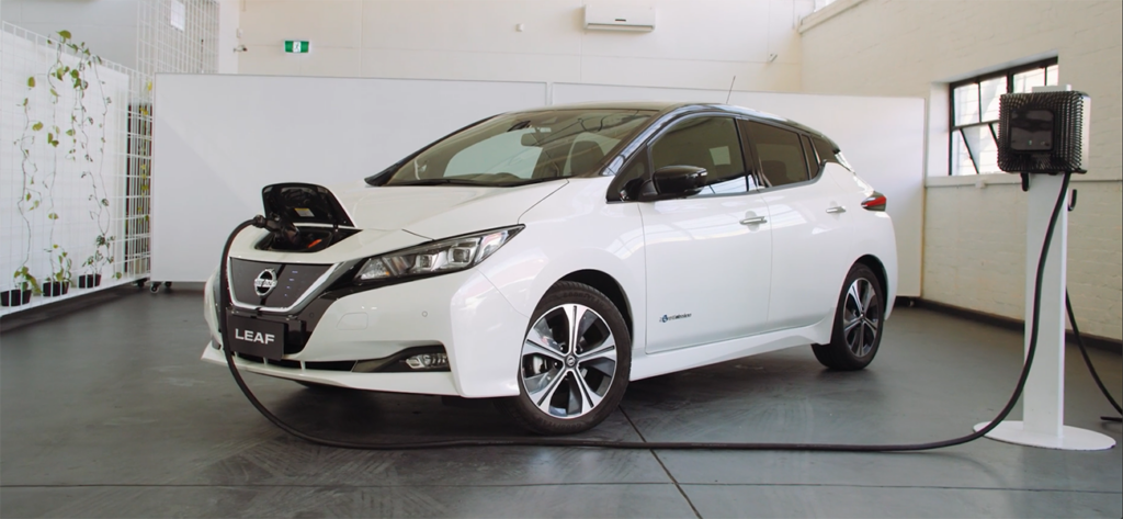
(Image courtesy of Nissan)
Types of bidirectional charging
Vehicle-to-grid (V2G) supplies energy from the EV battery pack to provide stability for the grid. This is a challenge in many parts of the world, especially at the extremes of summer and winter, and requires synchronisation with the grid.
One of the biggest challenges is providing electrical power quickly enough to avoid brownouts. Several countries, notably Australia, already use huge banks of batteries to respond rapidly to pending brownout conditions. EV batteries connected to the grid via bidirectional OBCs could contribute by delivering or consuming small amounts of energy to help balance supply under such conditions.
Electric cars are expected to hold 305 GWh of energy in 2025 and 540 GWh by 2030, making them a significant source of power. Harnessing this in a virtual power plant (VPP) via vehicle-to-load (V2L) enables users to power electrical appliances from the vehicle.
Utility vehicles are a prime example and can be used during recreation to power entertainment equipment, electric grills or even rice cookers while camping. Tradespeople and DIY enthusiasts can also use their electrical power tools in remote locations. This use case is currently more common in China and Asia-Pacific than in other areas.
Vehicle-to-vehicle (V2V) charging is a longer-term feature requiring bidirectional support from OBC implementations, along with standardisation so that it is compatible across vehicle manufacturers.
Vehicle-to-microgrid (V2M) applications see EVs interface with localised grid systems. The infrastructure typically includes renewable energy sources, storage systems and advanced metering.
Vehicle-to-home (V2H) works with home storage in a number of ways, either charging from solar panels or feeding energy back to home storage systems or direct to the building. This latter case requires synchronisation.
V2G Island Mode can provide electrical power to the home in the event of a power outage until grid power is restored. While this is theoretically possible with the availability of bidirectional OBC, it is a longer-term capability as it requires a method for the OBC to synchronise with the restored AC grid before the breakers are opened or closed.
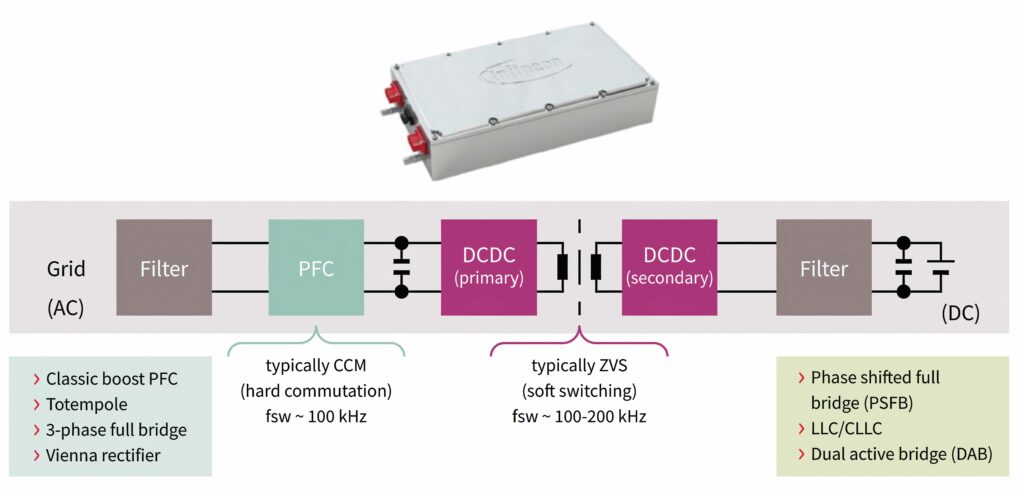
(Image courtesy of Infineon Technologies)
Vehicles
Many of the first EVs did not have bidirectional OBCs. The Nissan Leaf is the leading vehicle with two-way capability, and it also uses a CHaDeMo charging interface that limits its use with commercial chargers. However, recent vehicle launches with bidirectional OBC capability and CCS connectors include the Ford F-150 Lightning, Polestar 3, VW ID.4 and a protype from Jaguar Land Rover. The Hyundai IONIQ 5 and 6, Genesis GV60, Kia EV6 and Niro, Tesla Cybertruck support V2L applications.
(Image courtesy of Infineon Technologies)
Chargers
More chargers are emerging that support V2G, such as the Quasar 2 from Wallbox.
Back in 2020, ABB supplied its 11 kW bidirectional charging technology, specially designed for V2G, to DREEV in France, a joint venture between Électricité de France (EDF) and Nuvve, which specialises in intelligent charging for EVs.
Under the partnership, ABB will supply V2G bidirectional kiosks in France, with other installations in the UK, Italy, Belgium and Germany. One of the issues with bidirectional charging is that there is a requirement from the grid for a response time in milliseconds. The 11 kW ABB charger meets the most stringent grid timing requirements of a 10-15 ms response time.
The UK is running a trial of next-generation AC V2G charging technology.
Trial participants in the V2VNY project are using a 7 kW AC bidirectional charger with two sockets and a software package to optimise charging, which can be kept after the end of the project. The V2G technology enables EVs to be charged at times when electricity costs are low, and then put energy back into the grid or into a building, or even another EV, when electricity costs are higher.
This is one of the first V2G trials in the UK to use AC charging with the latest generation of EVs featuring V2L technology. Most previous V2G trials used Nissan and Mitsubishi vehicles with CHAdeMO DC charging technology. Trial participants need at least two EVs on their fleet that feature V2L technology from the brands of Genesis, Hyundai, Kia or MG.
The aim is to demonstrate, test and refine V2G technology. Jaguar Land Rover will provide prototype EVs for use in the trial.
“The UK has a huge and largely untapped battery storage capability in the form of over one million EVs that spend most of their time parked up. Using this resource can help reduce the load on electricity networks at peak times, as well as lowering costs and carbon,” said Mike Potter, CEO of CrowdCharge and DriveElectric, which is managing the project.
“This project will trial how the latest EVs can be used as mini power plants to benefit businesses, electricity operators and the country as a whole.”
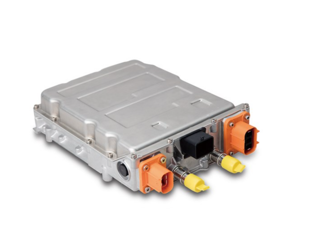
(Image courtesy of Delta)
Bidirectional OBC design
The design of bidirectional power converters are well understood, but there are a range of challenges involved in bringing them to market.
One idea is to develop two separate converters, each tuned to the specific needs of the application. The result, however, leads to a bulky solution with a high component count, making it challenging to meet the design needs of an automotive application.
One approach is a TotemPole PFC (TP-PFC) coupled with a Dual Active Bridge (DAB) topology, allowing the use of soft-switching and a low device count while also offering high efficiency and the necessary galvanic isolation.
These half/full bridges are connected to an inductor and high-frequency transformer that also sets the conversion ratio, respectively. The control method varies according to the demands of the application and the voltage range supported on either side.
One typical approach is to control both bridges using a complementary, pulse-width modulated (PWM) signal, typically from a microcontroller (MCU). Modification of the phase of the signals applied defines the direction of power transfer.
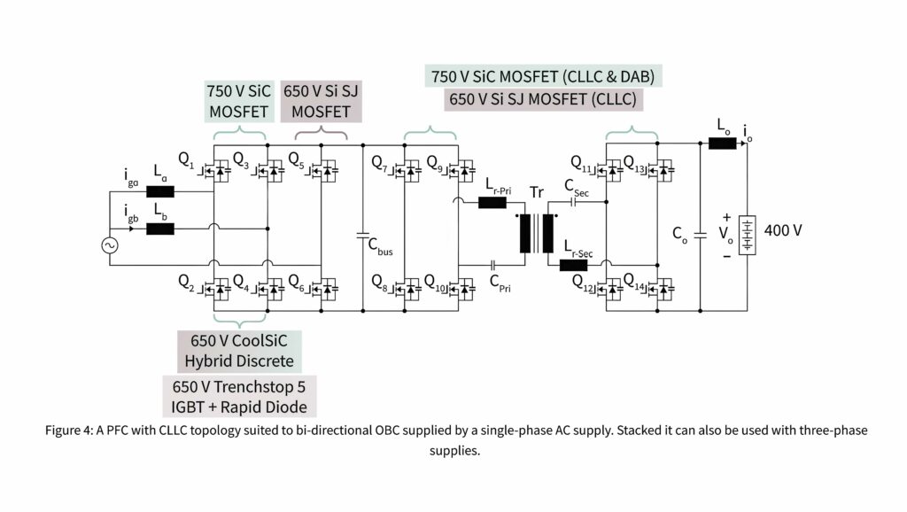
Another common topology is the CLLC resonant converter. This approach is suited to high-frequency switching, also thanks to its galvanic isolation and support of soft switching. This allows smaller, passive devices such as the magnetics and capacitors to be used, resulting in a compact design. The use of capacitors on both sides of the full bridges supports bidirectional current flow.
The basic design for a resonant CLLC converter is well-suited to a single-phase-input OCB design supporting common charger-power classes of between 3.6 kW and 7.2 kW.
Currently, 650 V silicon superjunction MOSFETs are well-suited, CLLC-based DC-DC converters connected to 400 V batteries, one of the industry’s current standard voltages. In the TP-PFC, 650 V Rapid Diode Automotive IGBTs are a fair performance, low-cost option with MOSFETs in the return path.
The CLLC approach is also suitable for three-phase OBC implementations by implementing a stacked converter. This allows OBC power classes from 11 kW (3 x 3.6 kW) up to 22 kW (3 x 7.2 kW).
OBCs supporting true three-phase AC grid inputs and higher voltage batteries, such as 800 V, benefit from the availability of 1200 V SiC MOSFETs. Traditionally, the domain of IGBTs, SiC MOSFETs enable higher switching frequencies to be used, leading to more compact and lower-weight designs.
The improved efficiency and related drop in heat dissipation provide designers with more flexibility in the overall design, thanks to innovative packaging that simplifies heat management. Like the single-phase version, three-phase designs can be configured in parallel implementations to support higher power delivery and shorter charging times.
LLC converter topologies have long been recognised as an optimal approach to DC-DC conversion in applications that convert AC grid power to a DC sink. Part of the attraction is their wide voltage adjustment range and handling of load variations.
The option to use soft-switching offers the secondary benefit of minimal electromagnetic interference (EMI) challenges while the transformer delivers the required galvanic isolation. An analysis of existing OBC designs and ongoing research into automotive chargers confirms this approach.
One of the challenges of an OBC is that the input side must handle a wide range of AC voltages and frequencies, depending on the region of the world where the xEV is used. The output side is, by comparison, more straightforward, as the load is known and remains unchanged over the xEV’s lifetime.
In addition to quantifying the input and output requirements, designers need to specify the power transfer planned and possible switching frequencies.
Resonant circuit components can be defined, including the stray inductance of the high-frequency transformer’s secondary. It is essential to work closely with an experienced transformer supplier at this stage to perform accurate simulations of the design.
However, a suitable control solution is required to handle both the real-time synchronous (closed-loop control) and asynchronous aspects (human/machine interface, monitoring and emergency shutdown) of the OBC.
Infineon has used its AURIX family of automotive microcontrollers (MCU) with an OPTIREG power-management integrated circuit (PMIC) chip for this.
The generic timer module (GTM) generates dynamic PWM signals for such applications with its 24-bit timer resolution and 5 ns granularity. This combination allows the AURIX to respond rapidly to voltage and current changes during OBC operation. The GTM running at 200 MHz can also support operation at up to 1 MHz OBC switching frequency if needed.
The software architecture accommodates the update of the DC-DC converter’s real-time control while including the control aspects demanded by a lower duty cycle.
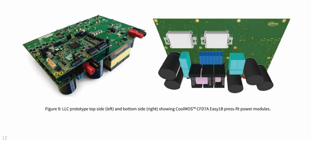
This design uses 650 V CoolMOS CFD7A superjunction power MOSFETs in Infineon Easy1B press-fit modules for the resonant LLC. These assisted in a simplified heat dissipation concept and allowed an easy exchange for testing purposes. EiceDRIVER devices control the gates, providing isolation and level shifting.
The LLC’s secondary side uses a synchronous rectification gate driver that triggers, based on the forward voltage of the body diode. To avoid damage at startup and shutdown, a hardware-based limit-checking and shutdown mechanism uses a sensor to implement a fast shutdown.
The resulting design can be produced on a six-layer, 70 μm, copper printed circuit board with surface-mount components on the top side and the through-hole components (capacitors, transformer and power modules) on the bottom. A control add-on board with an AURIX-based module allows the MCU to be placed on top of the LLC so that it can be exchanged if required. During testing, the design demonstrated efficiencies of around 96% to 97%.
The proof-of-concept approach described is a first step in developing OBCs according to existing unidirectional power-flow requirements and 400 V batteries.
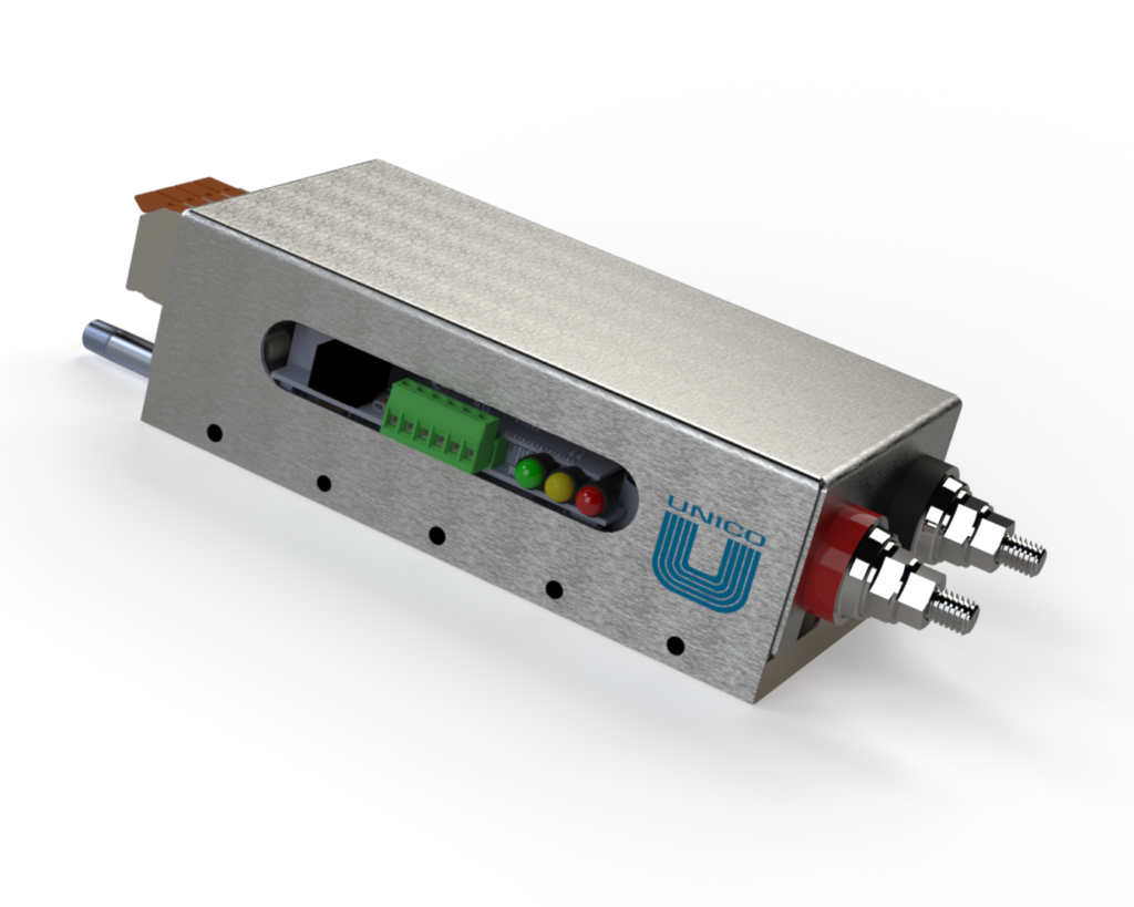
(Image courtesy of Unico)
Secondary side design
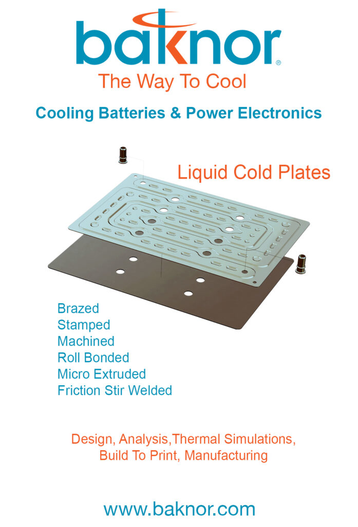
The move to support V2G and V2L requires only a few changes on the secondary side. The first is to enable the MCU to control the full bridge with gate drivers by replacing the synchronous rectification circuitry. The software also requires adaptation in the closed-loop control and support for setting power-flow direction. Finally, the secondary side needs the addition of resonant capacitors and an inductor. Support for higher battery or input voltages can be accommodated by moving away from silicon to CoolSiC power modules.
Infineon has worked with Delta Electronics in Taiwan on a three-in-one-system that integrates solar, energy storage and EV charging. The bidirectional system allows a maximum continuous current of 34 A and achieves peak efficiencies of more than 97.5% by using SiC devices.
Unico in Wisconsin has adapted its test system modules for bidirectional charging. They use SiC or GAN transistors at 200-300 kHz and this allows high-performance cell testing that is also extended to battery backed bidirectional charging.
“We are working on a project for bidirectional charging,” said John McKeen, vice-president of r&d at Unico.
The idea is to have a secondary battery energy storage system that takes 110 V from the grid and charges the battery pack to reach the 208 V level. This bidirectional system evens out the power requirement and allows a higher power charger without the need to upgrade the grid connection to the house.
“Our onboard charger will have V2G for a tier one OBC and DC-DC converter using the same platform as the cell test module. We use the transformers for input isolation for the power factor correction (PFC) to raise and lower the voltage,” McKeen added. This uses a proprietary flyback architecture to keep costs down.
(Image courtesy of Infineon Technologies)
Impact of V2G on batteries
To fully harness the benefits of V2G over the long term it is vital to consider EV drivers’ charging habits, and optimise the charging and discharging controls to minimise the impact of battery life, says Feyijimi Adegbohun, a researcher at Baylor University in Texas and now at General Motors.
He led a study that examines various V2X applications in North America and their effects on battery longevity, considering EV charging patterns. Additionally, it investigates advanced ageing-aware optimisation algorithms for managing bidirectional charging.
Adding EVs as dynamic energy storage systems in the grid through V2G introduces new operational complications, such as coordinating the driving and charging patterns of EV drivers.
Considering the charging patterns, trip duration, parking duration, charger type and charging location (e.g. office, home or public charging facility), vehicle type (e.g. heavy or light duty commercial, or passenger) are important in examining the potential value addition of EVs and charging infrastructure for a virtual power plant that delivers energy from a group of EVs.
Early demonstrations of V2G-based VPPs show the promise that V2G technology can play a significant role in reducing peak demand, as well as times when they may be crucial to grid resiliency.
EVs help to stabilise grid frequency by responding quickly to fluctuations in grid demand, which is why there is the millisecond response time requirement. This requires EVs to have fast-response charging systems capable of rapidly adjusting power output.
Key disadvantages of bidirectional charging include accelerated wear and tear on EV batteries due to frequent charging and discharging, which can diminish their lifespan and efficiency. Battery cell ageing implies irreversible changes that occur in a battery over time, and have adverse effects on battery performance and dependability.
Cell ageing can be quantified by two simple concepts: capacity fade and power fade. Capacity fade occurs when the total capacity of a battery (the total amount of energy that can be retrieved from the battery, and the round-trip efficiency of the charge/discharge cycle) also decreases over time.
Capacity fade is typically the metric used in determining the end of life (EoL) of a battery pack or cell by original equipment manufacturers (OEMs), which is typically 70% to 80% of the original capacity for EV applications. This type of ageing is correlated to the loss of active lithium inventory with a decrease in the active material capable of storing energy by lithiation/delithiation processes.
Power fade (sometimes referred to as impedance increase) refers to the decrease of the power that a battery can deliver at the rated voltage, usually correlated with calendar time, as well as with charge/discharge power levels used in the batteries’ history.
As the term ‘impedance increase’ implies, this correlates to a rise in the equivalent series internal resistance of the cell or pack, which is a major factor in the power calculation or state-of-power (SoP) determination of an EV. Power fade occurs primarily as a consequence of growth of the solid-electrolyte interphase, which causes mass transfer of the lithiation/delithiation to decrease, thereby resulting in the mentioned increase in battery internal impedance.
Both fade processes occur primarily due to side reactions within the battery and they are exacerbated by more strenuous battery operating conditions in bidirectional charging.
The ageing mechanisms of batteries can also be classified into two different types: calendar ageing and cycle ageing.
When the battery is loaded, that is the battery is charging/discharging, the capacity fade in this scenario is considered to be cycling ageing. Cycling ageing is characterised by the different operating conditions of the battery, such as the charging rate (C-rate), charge throughput, depth-of-discharge (DoD) and temperature.
Given the complexity and convoluted nature of battery degradation mechanisms, advanced methods of modelling and detecting ageing have been proposed.
For EV bidirectional charging specifically, it is important to understand the use case and duty cycles that the batteries will operate in to assess the likelihood of degradation, and thereby mitigate the effects of this by ageing-aware optimisation of the battery controls. Schwenk integrated an ageing-aware model into a smart charging use case and compared it with measurements of real EV charging. The results show that disregarding battery ageing underestimates EV operating costs by approximately 30%.
The impact of battery operational parameters, such as state of charge (SoC), depth of discharge (DoD), operating temperature and charge throughput (C-rate) cannot be overstated.
Cell degradation as a function of the cycles shows that limiting the DoD to small ranges and maintaining the battery at a 50% SoC can enhance battery life by 44-130%, focusing solely on ageing caused by driving patterns.
Additionally, when considering the impact of calendar ageing, it was evident that this factor constitutes a significant portion of overall battery ageing. By keeping the battery at 15% SoC during periods of inactivity and minimising the duration at high SoC levels, the effects of calendar ageing on the battery could be significantly diminished.
The specific chemistry of a cell will also impact its bidirectional charging application and subsequent ageing mechanisms.
Capacity loss was most significant at 60 C and higher storage voltages, and this was evident in NMC, NCA and LTO cells. NMC and NCA cells at 60 C and high storage voltage experienced complete breakdowns due to their current interrupt mechanism being triggered.
Cell ageing with bidirectional charging
Different cell types exhibited varying responses to calendar ageing. For example, LMO cells at 50 C showed minimal degradation, while LTO cells had the highest capacity decrease at high storage voltages, but the least increase in internal resistance. This could, for instance, indicate that LTO batteries might not be great for backup power applications where a high SoC/high storage voltage is needed over long durations of time (120 days), because of the infrequency of backup events and the desire to retain high capacity in the batteries.
Implementing V2G twice a day led to a 75% hike in capacity loss and a 10% rise in resistance. Even reducing the V2G to once a day resulted in a 33% acceleration in capacity loss and a 5% increase in resistance.
This shows the significant negative impact of V2G on cell health under mild conditions, potentially reducing the battery pack’s lifetime to under five years. Interestingly, delaying charging using grid-to-vehicle (G2V) compared with immediate charging had minimal impact on capacity retention (<1%) and a limited effect on resistance (<5%) at room temperature.
Charging strategies such as time-shifting charging combined with smart charging schemes with V2G, discharging some of the battery capacity to the grid/load to precondition the battery to an optimal SoC, are capable of mitigating the total ageing process from 7.3% to 26.7% for the first 100 days of operational life, and gradually vary to 8.6% to 12.3% for one-year continual operation compared with the reference standard charging approach.
There is an absence of experimental studies to reach a consensus on the degradation effect of smart charging concepts, but those that exist are not simple to accomplish as they can take years and may even be obsolete by the time they are completed due to the rapid evolution of battery technology, applications and controls.
Modelling of lithium ion batteries indicates that keeping them at a high state of charge without discharging, such as a parked vehicle at a high SoC that does not participate substantially in a V2X process or a vehicle that repeatedly cycles (whether by driving or participation in a V2X process), leads to a lifetime in the order of 10 years.
As bidirectional charging continues to play a pivotal role in enhancing grid flexibility and stability through V2X applications, battery life prediction is increasingly influenced by data-driven approaches, and state-of-the-art AI and machine-learning models. This includes the use of sophisticated, self-attention mechanisms, and ensemble models that integrate these mechanisms with long short-term memory (LSTM) networks to develop more precise ageing models for batteries, alongside real-world telemetry of battery parameters undergoing use in such applications.
These models aim to establish quantitative thresholds for battery ageing acceleration, as these models become more effective and accurate when trained with a relatively large corpus of data. There is a growing emphasis on designing universally adaptive, model-based or data-driven ageing-detection frameworks, which are essential for improved battery diagnostics and lifetime estimations – key factors in boosting the widespread adoption of bidirectional charging in VPP applications.
These AI-driven approaches are not only augmenting current understanding and methodologies, but also paving the way for more resilient and efficient battery usage in the evolving landscape of renewable energy and smart grid technologies.
Conclusion
Bidirectional charging and V2X configurations enable EVs to become dynamic, value-adding participants in grid operations. This research review offers key insights into existing capabilities, applications, and real-world projects at the customer and utility level by exploiting vehicle batteries for additional grid flexibility.
However, ageing mechanisms induced by repeated charging/discharging must be addressed through ongoing fundamental studies, advanced battery management algorithms, improved component designs and demonstration at scale to cement the future of bidirectional charging. Significant progress on understanding ageing-reliability trade-offs will be integral for EVs and charging infrastructure to unlock their full potential within an increasingly complex energy ecosystem.
ONLINE PARTNERS


